
Thursday, November 17, 2016
Finished the aileron push tubes - 6 hours
Bit of a long couple days. I've primed the outside of the tubes, and once dry I covered the primer with white automotive paint. I inserted the bearings and jam nuts in the tubes. Everything is identical to the when compared to the full size details on the plans.

Sunday, November 6, 2016
More aileron push tubes - 6 hours
Using the V-shape block in the drill press, I began to drill the inserts in the push tubes. First I started off with #40 pilot holes, then I upsized the, to #30 holes.


Next I cut the steel aileron tubes to size.
Again, I used autocad to draw a template of where the holes needed to go and taped the template onto the rod.


It was now time to prime the insides of the tubes. I fastened a piece of scotch bright to a dowel and inserted it into the drill. This polished and cleaned the inside of the tubes.

Once cleaned and ready. I taped all the holes and dumped wet primer in the tubes. I rolled them around a bit and then dumped the excess out. Next I wanted to get the inserts in the tubes before the primer dried. I used a gun and bar to set the steel tubes.


Saturday, November 5, 2016
Started aileron push tubes - 2 hours
I started in on the aileron push tubes. There is a bit of controversy of the length on these. I suppose that I wont really know what the truth is until I install the wings on the plane. I decided to carry on with the plans and see how it goes. If I have to redo them in a year or two....oh well.

I cut them down with a hack saw, and then carefully took them down to the appropriate dimension with the sanding station. I had build a jig to ensure that all was level and square.

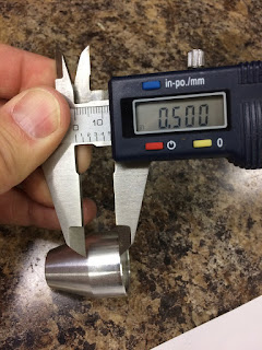
Next I need to figure out where to put the holes in the push tubes. I measured the inserts that go into the tubes, they insert 0.5" so the rivets would need to be installed 0.25" in from the edge of the tube.
I decided it was best to draw out a template on autocad which would help show the 0.25" offset as well as the proper offsets around the tube.


Now I could easily see where each hole needed to go.

I cut them down with a hack saw, and then carefully took them down to the appropriate dimension with the sanding station. I had build a jig to ensure that all was level and square.

Next I need to figure out where to put the holes in the push tubes. I measured the inserts that go into the tubes, they insert 0.5" so the rivets would need to be installed 0.25" in from the edge of the tube.

I decided it was best to draw out a template on autocad which would help show the 0.25" offset as well as the proper offsets around the tube.


Now I could easily see where each hole needed to go.
Sunday, October 30, 2016
Mounting the pitot heat controller - 3 hours
One of the ideas that I liked while researching other builds was mounting the heat controller in the bay beside the aileron bellcrank. I figure the best way to align things was to cut out a template and use that as a drill guide on the wing rib rather than try to work with the actual heat controller.


Once I was satisfied with the alignment and the position, I drilled holes for #6 screws. Next I had given some thought to how I wanted the controller to be mounted to the rib. Most have screws but are accessed from the inside. I figured if I installed nutplates on the controller, I could easily install/remove the controller by having screws accessible from the access plate. So that's the direction I headed.


Once I was satisfied with the alignment and the position, I drilled holes for #6 screws. Next I had given some thought to how I wanted the controller to be mounted to the rib. Most have screws but are accessed from the inside. I figured if I installed nutplates on the controller, I could easily install/remove the controller by having screws accessible from the access plate. So that's the direction I headed.


Saturday, October 29, 2016
More Pitot work - 3 hours
More monkeying around with the pitot. Ive pulled in the lines and through the new bell crank bracket that I had made. At first it looks good, but then I see the top most line is awfully close to the bellcrank.


I may need to reroute that topmost line down a hole. The clearance is great if I did it that way. I also notice that the AN509-6R6 screws are just a bit too long for the pitot so I will revise these to AN509-6R5 screws (5/16" length)

I took the opportunity to prime the countersunk holes in the mast.

Looking good.

Friday, October 28, 2016
Drilling the Pitot Mast - 3 hours
I've been looking forward to drilling the pitot into the mast for some time now. I've looked at a number of installations and I think that I have wrapped my head around it enough to tackle the task.


 I completed tapping treads for #6 screws. Now I just need to countersink the mast. I'll do that tomorrow. Getting late tonight, and it's never good countersinking when tired.
Straight away I can finally see where everyone mentions the 'thick part' of the pitot. I will need to ensure that the pilot holes for the #40 drill bit will be centered on these. Easy enough to do if I drilled directly into the pitot. But the tricky part is that I need to drill through both the mast and the pitot so transferring the holes on the outside the mast will be tough given the curved surfaces and the thickness' involved. So I began to mark out all lines on the pitot with the idea that I will transfer them up to the mast.
When inserting the Dynon pitot into the Safe Air 1 mast the slip fit is a little loose. Enough to make me feel nervous about drilling it that way. So I used a piece of electrical tape wrapped around the pitot (1 layer). The fit was not snug but found 2 layers was too thick. So I used 1 layer of electrical tape and 1 layer of masking tape...nice and snug.
Then I went to work transferring the lines up the mast. Also placing the holes dead centre between the 0.700" overlap between the mast and pitot.
I didn't not feel 100% comfortable that I had transferred the lines right. There is so many ways that errors could have crept in. So I made a paper template and marked out the lines on that and compared that with the markings on the pitot and the mast. Everything seems to be in order. It's still not the most precise way but at some point I just had to roll with it.
I set up the vice on the drill press and drilled the holes with #40 pilot hole. Once I was happy with that, I opened up the holes to #32. I then pulled it all apart and inspected. I am very pleased with the aft holes. Dead centre. The forward holes are a bit off centre (maybe 1/32") but still in the thick part of the pitot metal. But considering how narrow the forward most 'thick' parts are, I think I did just fine.
Looking back on it I suppose I could have pulled out my pitot hole template. I could have slipped that over the pitot and marked the lines and used that to transfer to the mast. Who knows it may have worked better, may not. In the end I'm happy with the result.
Thursday, October 27, 2016
More drilling the Aileron counterweight pipe - 2 hours
I wasn't sure the best way to open up the #40 holes in the counterweight. I decided to set up to drill the pipe on the press. I will be able to put my drill jig to good use.

That was easy. Next step was to cleco the pipe back into the aileron, and drill out the #30 holes in the skin. Worked very well.

Once both ailerons were drilled. I needed to disassemble the leading edge and complete the #30 holes that are drilled from the backside.

I then disassembled the parts and looked everything over. All looked good, but I wasn't happy with some of the holes in the small tabs of the A-705 ribs. Some were slightly oblong just due to the way they were match drilled. So...It was an easy decision to replace with new. They are pretty cheap $6/each. The 'ol RV two step. Two steps forward, one back. lol.
I also placed a small order to cleveland for a CS4-4 countersink (The irony is I just ordered on a couple of weeks ago for a friend...Now I find that I need one...hahah)
Subscribe to:
Posts (Atom)