I had ordered another F-719-L stiffener from Van's and went to work re-drilling and fitting the whole piece. I am now becoming a master a doing these...This is my third left stiffener.
Long story short. It came out perfect. Holes for the side skins and rudder pedals all drilled and are excellent.
I'm still concerned with a bit of an inward bow where the joggle is.
Monday, August 31, 2020
Sunday, August 30, 2020
Match drilled the F-772 bottom skin - 2.5 hours
Thinking on what to do next, I figure at some point I need the get the F-772 bottom skin in place. And right now seems like a good time.
Before I started, I felt it wise to drill a couple keeper holes to aid in getting the skin fitment correct.
I choose the #40 holes towards the aft ans one of the #30 holes.

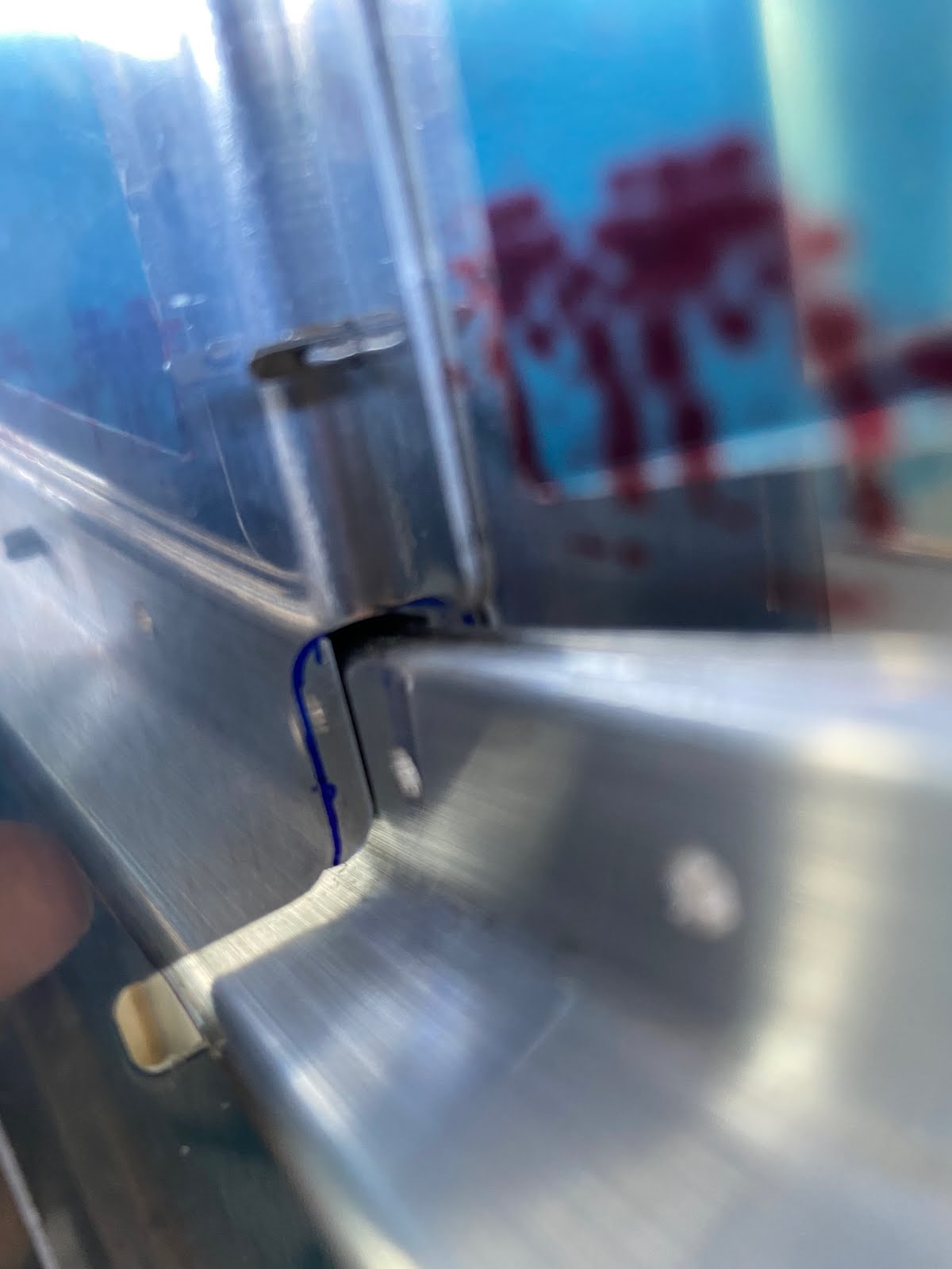
Then I began to drill all the holes. This included the holes being drilled through the lower engine mount. I was concerned about the edge distance here as there is very little room to work with. But as you can see a do have enough edge distance. In fact the blue line is drawn at 0.225" rather than minimum edge distance at 0.219" just for a bit extra.


All of the holes drilled and the floor skin is cleco'd

Before I started, I felt it wise to drill a couple keeper holes to aid in getting the skin fitment correct.
I choose the #40 holes towards the aft ans one of the #30 holes.

Then I began to drill all the holes. This included the holes being drilled through the lower engine mount. I was concerned about the edge distance here as there is very little room to work with. But as you can see a do have enough edge distance. In fact the blue line is drawn at 0.225" rather than minimum edge distance at 0.219" just for a bit extra.


All of the holes drilled and the floor skin is cleco'd

Saturday, August 29, 2020
Drilled the F-902 bulkheads for the second time - 3 hours
With the recent Vans shipment, I ordered new F-902 bulkheads, since drilling them to the F-7101 gear attach web can be quite tricky.
I already have the spacers cut for this area out of 0.032" but the spacers do come quite close and touch the longerons & stiffeners. So I decided to mark them and give them a notch for clearance to help ensure good fit.
UPDATE: Do not follow the installation picture below. It is very important that you use a piece of 0.040" scrap between the F-719 longeron and the F-770 side skin. Later when I went to install the floor skin, I noticed that the holes to the gear attach web are slightly offset.


As you can see the fit is very close and I fear that it may prevent the gear web from sitting flush against the angles.

With a bit of work on the 3M wheel the notches are easily made.

I was then ready to begin drilling the holes to the F-7101 gear attach web.

I already have the spacers cut for this area out of 0.032" but the spacers do come quite close and touch the longerons & stiffeners. So I decided to mark them and give them a notch for clearance to help ensure good fit.
UPDATE: Do not follow the installation picture below. It is very important that you use a piece of 0.040" scrap between the F-719 longeron and the F-770 side skin. Later when I went to install the floor skin, I noticed that the holes to the gear attach web are slightly offset.

As you can see the fit is very close and I fear that it may prevent the gear web from sitting flush against the angles.

With a bit of work on the 3M wheel the notches are easily made.

I was then ready to begin drilling the holes to the F-7101 gear attach web.

Wednesday, August 26, 2020
More F-719 work - 1 hour
So when drilling the 2nd rudder bearing block position on the F-719-L stiffener. The aft mounting holes is just a tad tight for fitment (Remember I reamed the holes to 3/16"). At the end of the day, I felt it better to redo the part since it is fairly easy to do now. So I ordered a new F-719-L stiffener from Vans, but when it arrived today, the fit is very poor when compared to the right side.


To make it fit better, I tried to bend the angle more rather than fabricate shims for such a large gap. Needless to say I ruined the angle trying to bend it more. (Surprise, Surprise). I'll order more F-719-L stiffeners in hopes I can make a near perfect one.


To make it fit better, I tried to bend the angle more rather than fabricate shims for such a large gap. Needless to say I ruined the angle trying to bend it more. (Surprise, Surprise). I'll order more F-719-L stiffeners in hopes I can make a near perfect one.
Tuesday, August 25, 2020
Trimming the rudder brace and pedals - 2 hours
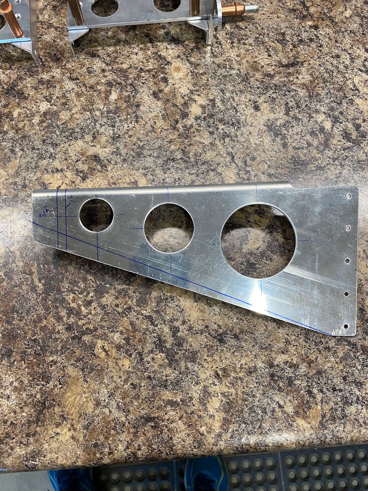
Little work to be done to the assembly. I need to trim the rudder brace as it is a bit long, however since I drilled the 1" lightening hole I cannot trim as much material as I would like. Some other build logs have suggested trimming 1" in from the aft end. But as you can see the 1" line is a bit close to the hole for my liking. I then drew a 3/4" line and that looks a bit better.

I trimmed at the 3/4" line as well as the bottom of the brace according to the dimensions on the plans. (The part comes a bit bigger/deeper).


Lots of material there for the most aft mounting position. As you can see, the 1" lightning hole is much more aft than needed, hence why in retrospect I shouldn't have cut that hole.
Next, I need to trim the rudder pedals to help lighten them. This is fairly straight forward.


Saturday, August 22, 2020
Installed the rudder pedal brace - 6 hours
Finally I seem to be back into the proper groove now that I have the rudder pedals sorted. Now I can get back to installing the centre brace.
With the bow in the pedal tubes straitened, the fit of the center brace is much better now.

After taking some time to check the fit, I then drilled the brace to the firewall angle using a #30 bit and my 90deg drill attachment. It was as simple as it sounds.

Now comes the tedious part. Drilling the brace for the bearing block. It takes a bit of time to get things sorted and aligned and then I was able to place the first mounting hole. I finished all holes on the drill press with a reamer so that means I needed to mark the hole, remove, drill, install, then repeat. Tedious, but the results are excellent.

Now I need to enlarge the cutout for the firewall recess. I did make an initial cutout, however what's shown on the plans, is not exactly correct. The plans call for a 1 3/8" cutout to be made to the part that's already supposed to have a small cutout. The part they give you has no cutout at all. so I bit of thinking, measuring and cutting is needed here.At this point I am close

Little bit of filing and final fitting things are looking good.

Once the fit was correct and complete, I then drilled the lightening holes as suggested in the plans. I did all three, but in retrospect I should have omitted the 1" cutout, it would allow me to trim the brace a bit more. You will understand when I show you how I trim the brace.

Friday, August 21, 2020
More rudder and brake pedals - 3 hours
I really think deep down I love working on these pedals. Just can move past them.
The new rudder pedal arrived this week so I went to work straightening the bow'd tubes trying very carefully not to kink them. I use the wood stairs in the garage as the are open type and spruce (soft wood) and I wedge the tube in the opening and I am then able to bend them into a relatively straight shape.

I had also ordered one new brake pedal since one of mine was quite scratched. I matched drilled it to my angles and then I took some time to clean up the lightning holes in all 4 pedals. that's more work than it sounds.

Tuesday, August 18, 2020
More brake pedal work - 1 hour
Saw this today and had a good laugh....

I'm kind of slowed down on my build until I receive new parts. So I putz'ed on the brake pedals. I countersunk all the holes for the AN426 rivets. Better than doing nothing I guess.

Monday, August 17, 2020
The rudder pedal 2-step - 2 hours
Unfortunately a very short build day today. Grrr
One step forward....two back.
I started in on the build session by setting up all of the dimensions on the F-6118 rudder pedal brace. I then did an initial cutout for the firewall recess.

Once I was happy with things, I then drilled the holes that are to attach the brace to 1/8" per the drawings. Next I need to clamp the brace onto the firewall and begin the final adjusting so that I can complete the rest of the drilling on the firewall.
While messing with the fit, I noticed that I wasn't getting a real nice fit/alignment. Long story short, the rudder pedals have a bow in the long tubes that is affecting how everything aligns. I'll save you the boring details and lets just say that I kinked the WD-655-R-PC rudder pedal tube while trying to straighten the bow. The kink wasn't horrible but I just don't want to live with that. That's an expensive part order (Add in part, exchange and shipping and it's not cheap! ~$250cdn). Yeeesh.
Sunday, August 16, 2020
Installed the rudder pedals - 2 hours
Didn't manage to spend a whole lot of time in the garage today, however it was most defiantly a full plane day. Today was an EAA Meetup out in Wetaskawin.
My buddy Mike came over and we headed out to the EAA meet and someones hanger. Fortunate for me there was some really nice F1 rockets out there that I was able to drool over.

As well, I got to take a good look at some other planes as well as a beautifully painted RV7. Also one of the members has a RV10 that I got a good peak at and he was able to give me some advice on avionics and engine choices which I appreciated

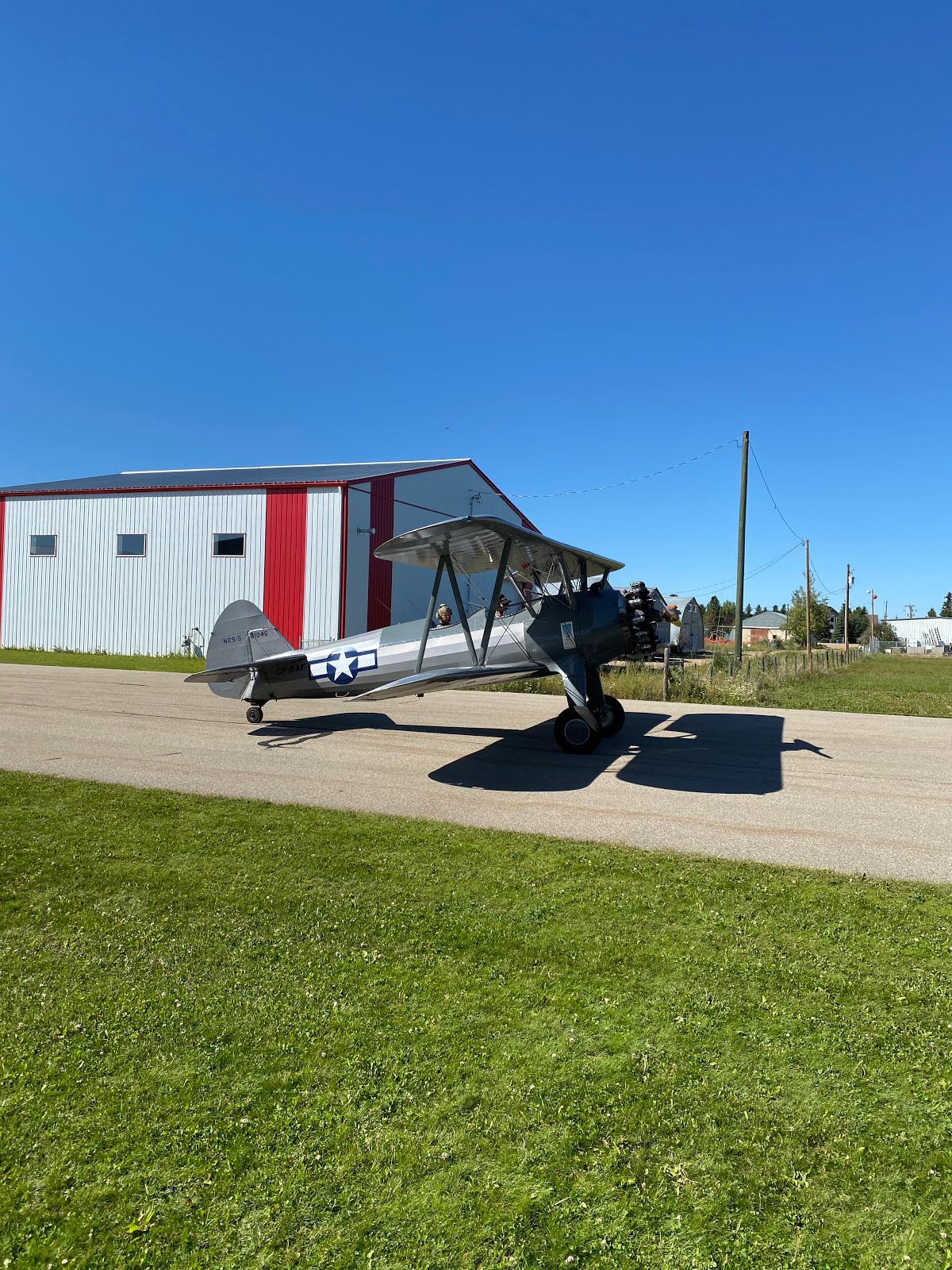
Oh...A Stearman!

So needless to say I didn't get a long build session in today but I was certainly motivated to get going when I got home.
I started in by removing the Bearing blocks to the F-719 stiffeners. I clamped the assembly to the bench and used the hand drill to start the holes. I finished the holes on the drill press using a reamer.


When all was done...I installed the rudder pedals into the fuselage.
My buddy Mike came over and we headed out to the EAA meet and someones hanger. Fortunate for me there was some really nice F1 rockets out there that I was able to drool over.

As well, I got to take a good look at some other planes as well as a beautifully painted RV7. Also one of the members has a RV10 that I got a good peak at and he was able to give me some advice on avionics and engine choices which I appreciated

Oh...A Stearman!
So needless to say I didn't get a long build session in today but I was certainly motivated to get going when I got home.
I started in by removing the Bearing blocks to the F-719 stiffeners. I clamped the assembly to the bench and used the hand drill to start the holes. I finished the holes on the drill press using a reamer.

When all was done...I installed the rudder pedals into the fuselage.
Saturday, August 15, 2020
Installing brake master cylinders - 2.5 hours
Another day spend messing with the rudder pedals. This time I have set up the rudder pedals on the table so that I could install the master cylinders for the brakes. I am very pleased with how well the AN3-56 bolts tuned out. Very smooth motion on the brakes.

It took me some time to figure out how I wanted the Grove master cylinders set up. Being that they are adjustable, I spent some time messing with the turnbuckle until I was happy. Next I used one of my short bits from my 90deg drill and used that to mark the 3/16" hole that needs to be drilled in the brake pedal horn.

I then removed the brake pedals, and disassembled them. The drill bit makes a nice arc "scratch" that I can easy find centre on. Then I drilled them to 3/16". I reassembled everything and it works great!

Tuesday, August 11, 2020
More rudder pedal work - 2.5 hours
I've been giving a lot of thought as to how to drill these angles, I finally decided that the way I was going to do it is on the drill press, on an angle.
I scanned in the rudder pedal into AutoCAD to find the angle geometery of the pedal. Using this information I was able to create a template that I could use as a setup for the drill press...to drill the correct angle.
It is a tedious process but I managed to clamp each F-6115C angle to a wood block and then open up the #30 holes step by step to a 3/16" reamed hole. The result once the assembly is cleco'd together is that the holes lined up fairly well....very small adjustments needed to make the bolts fit very well.


I then started trimming the 45deg angles at the bottom of the pedals.

Monday, August 10, 2020
More work on the rudder pedals - 1 hour
I've ordered the long AN3-56 bolts for the rudder pedals rather than use the short individual bolts from Van's. I hope that I can maximize on the smoothness of the break action by making this modification. (I really hope so because the bolts are not cheap...~$17 each).
So I used the F-6117A side plates to mark and drill the pilot holes for the AN3 bolts in the angles. I've been giving some thought as to how best to drill these as the holes need to be slightly angled to allow proper alignment of those long AN3 bolts. To help prepare this, I drilled the #30 pilot holes using the 12" bit to help get that proper alignment going.

I have a round file that exactly a #30 diameter so I used that to help get the correct alignment.

I am going to have to give some more thought on how to get these holes drilled so they align properly.
Sunday, August 9, 2020
Worked on rudder pedals - 8.5 hours
Since I am still waiting for my new F-902 bulkheads (sent snail mail). I jumped to the next section of the build being the rudder/brake pedals. It was a good build session, managed to put in a few hours today however the progress was slow as working with the plastic is tedious.
From what I have learned about drilling the flap blocks, I am more prepared to drill these pedal blocks. First step is that I made a template out of aluminum and placed #40 pilot holes in the correct location.

These get clamped to the top, and then the bottom of the plastic block allowing me to use the palm drill to correctly place a #40 starter hole....This starter hole is just a few thousandths deep and is meant to just mark the top of the plastic as a guide for drilling on the drill press.

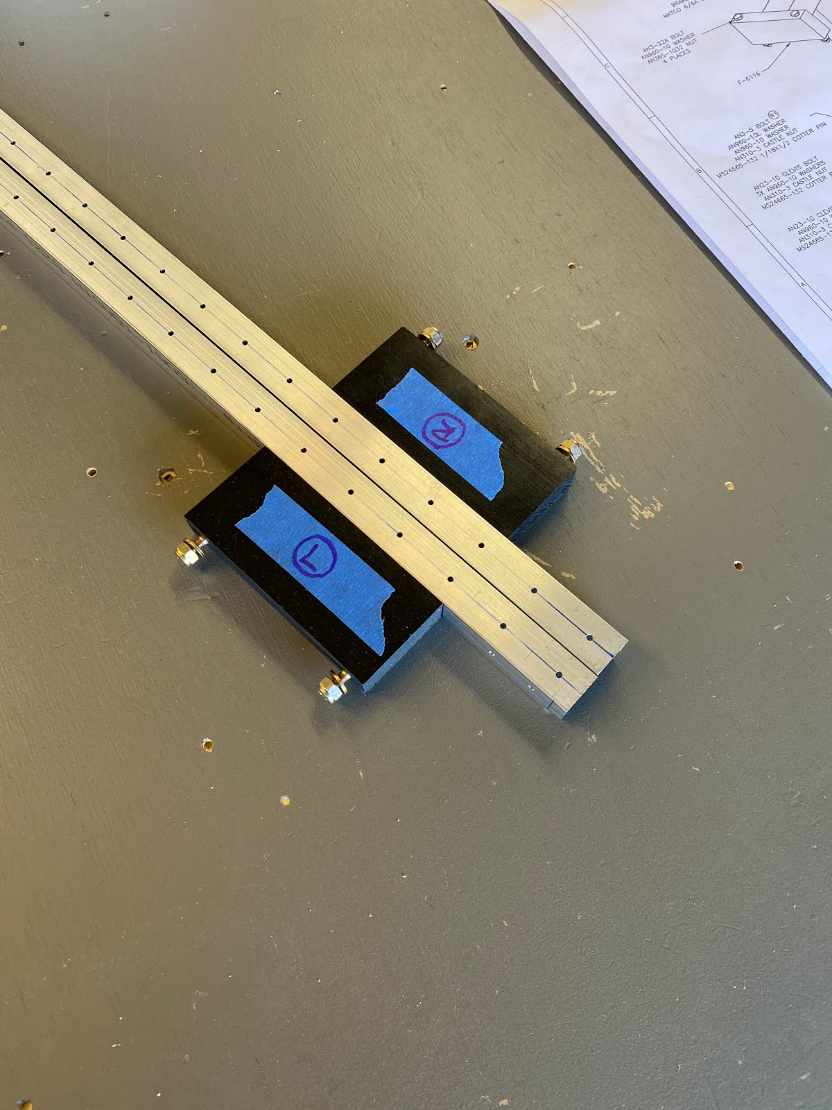
Once I have the holes "Marked" I then set-up the drill press. Making sure the platform/drill bit is all square. I used 2"x 2" oak blocks to clamp everything down to the drill press platform. Now, comes the tedious part. Once happy with the drill press alignment. I drilled the holes with #40 jobber bit but only half-way through. Then I flip the block over and do the same - drill halfway through. I use the jobber bit as its shorter, more stiff, and less likely to wander when drilling through thick plastic. Drilling halfway reduces the potential for wander.

I worked through #40, #30, #2, #15 this way...Only halfway through and flipping it to do the other side. Each time I am able to check that the holes align perfectly when looking through the hole.

I then finished the holes using a #10 bit set rather loose in the drill jig but drilling all the way through this time. The result is excellent...I have a good "pilot" hole that allows the #10 bit to track all the way through and not wander.
Next tedious (scary part) that I was dreading was to cut the F-6115 center pedal block. I finally decided that cutting these on the bandsaw was the way to go, but I am nervous about it as I have a cheap Ryobi band-saw and the blade isn't that rigid. So I clamped a large oak block to the band saw as a guide.

The result is really good. Uhhh, big worry off my mind that it all went well.

I moved on to cleaning up the rudder pedals and fabricated the F-6117C angles for the pedals.


From what I have learned about drilling the flap blocks, I am more prepared to drill these pedal blocks. First step is that I made a template out of aluminum and placed #40 pilot holes in the correct location.

These get clamped to the top, and then the bottom of the plastic block allowing me to use the palm drill to correctly place a #40 starter hole....This starter hole is just a few thousandths deep and is meant to just mark the top of the plastic as a guide for drilling on the drill press.

Once I have the holes "Marked" I then set-up the drill press. Making sure the platform/drill bit is all square. I used 2"x 2" oak blocks to clamp everything down to the drill press platform. Now, comes the tedious part. Once happy with the drill press alignment. I drilled the holes with #40 jobber bit but only half-way through. Then I flip the block over and do the same - drill halfway through. I use the jobber bit as its shorter, more stiff, and less likely to wander when drilling through thick plastic. Drilling halfway reduces the potential for wander.

I worked through #40, #30, #2, #15 this way...Only halfway through and flipping it to do the other side. Each time I am able to check that the holes align perfectly when looking through the hole.

I then finished the holes using a #10 bit set rather loose in the drill jig but drilling all the way through this time. The result is excellent...I have a good "pilot" hole that allows the #10 bit to track all the way through and not wander.
Next tedious (scary part) that I was dreading was to cut the F-6115 center pedal block. I finally decided that cutting these on the bandsaw was the way to go, but I am nervous about it as I have a cheap Ryobi band-saw and the blade isn't that rigid. So I clamped a large oak block to the band saw as a guide.

The result is really good. Uhhh, big worry off my mind that it all went well.

I moved on to cleaning up the rudder pedals and fabricated the F-6117C angles for the pedals.


Saturday, August 8, 2020
Constructed the Van's Aircraft Sign
Decided to take put aside the airplane build and I just messed around with putting the Van's Aircraft sign box together.Turned out really nice and now I can put it on display in my office at work.


Subscribe to:
Posts (Atom)