Showing posts with label Brakes. Show all posts

Thursday, July 20, 2023

More brake line fitting - 3 hours

 I went back to Mopac and purchased 2-14" lines for the park brake to pedals, and 2-36" lines for the pedal to pedal connection. 


Do there is no doubt that the 14" lines are the correct choice over the 16" lines. However I am a bit concerned with the length of the 36" lines. They look right, and run nicely to the other pedal with gentle sweeping bends, however when moving the pedals back and forth, I see that I am getting some rubbing of the lines on the brake pedal tubes. To help combat this, I designed and 3D printed brake line clips to help separate lines. After installing them, they certainly do much to keep lines from rubbing together, however I'm still having some issue with the right pedal. I just need a little more slack in the lines. I might need to go back to 38" lines. 


Wednesday, July 19, 2023

Started installation of flexible brake lines - 1.5 hours

 Before I get the front deck into place, I want to ensure that I have all of the brake lines on the rudder pedals sorted out. The local auto race shop Mopac, which is similar to Summit Racing in the US sells stainless braided PTFE brake lines.  

I ended up purchasing 2-16" lines for the park brake to pedals. And 2-38" Lines to run from pilot pedal to co-pilot pedal. On initial fit, both look a tad long.


Perhaps I should go to the next size down line 14" and 36" respectively.


 One item that I did, was to route the brake lines through the lightening hole in the brake pedal brace. I 3D printed a type of 2-piece interlocking grommet/line holder out of black PLA. It took a revision or 2 to get it right. Holds the lines nicely in place.


Saturday, July 1, 2023

Small fixups and installing the brake pedal assembly - 5 hours

 Before I can start prepping the front canopy deck for assembly. I need to put a bit of work into the cabin area and brakes. I did not finish this area off originally as all of the drilling of the front deck results in a bunch of metal filings I didn't want all over the fuel system and brake system. 


 I removed the center cover to expose the forward brake lines. During the original installation, I didnt get one of the plastic retainers installed as I was short 1 half. So, I took care of it. 


 Now...The issue I was having with my brake pedestal install last year is that I had an amount of play in the WD-655L/R brake weldments that would (in work case scenerio) allow the two master brake cylinders to rub against each other. To combat this, I need to install a small washer in the F-6116 bearing blocks to limit the amount of potential movement I can get between the two weldments. 

Last year I had cut a few 1 1/4" dia x 1/4" thick discs out of HDPE plastic. I just need to trim them down to proper size. Using the 3D printer once again, I made a template/guide so I can trim the white HDPE to a tight press fit in the bearing block. One 1/4" spacer is installed in opposite ends for each F-6116 weldment.


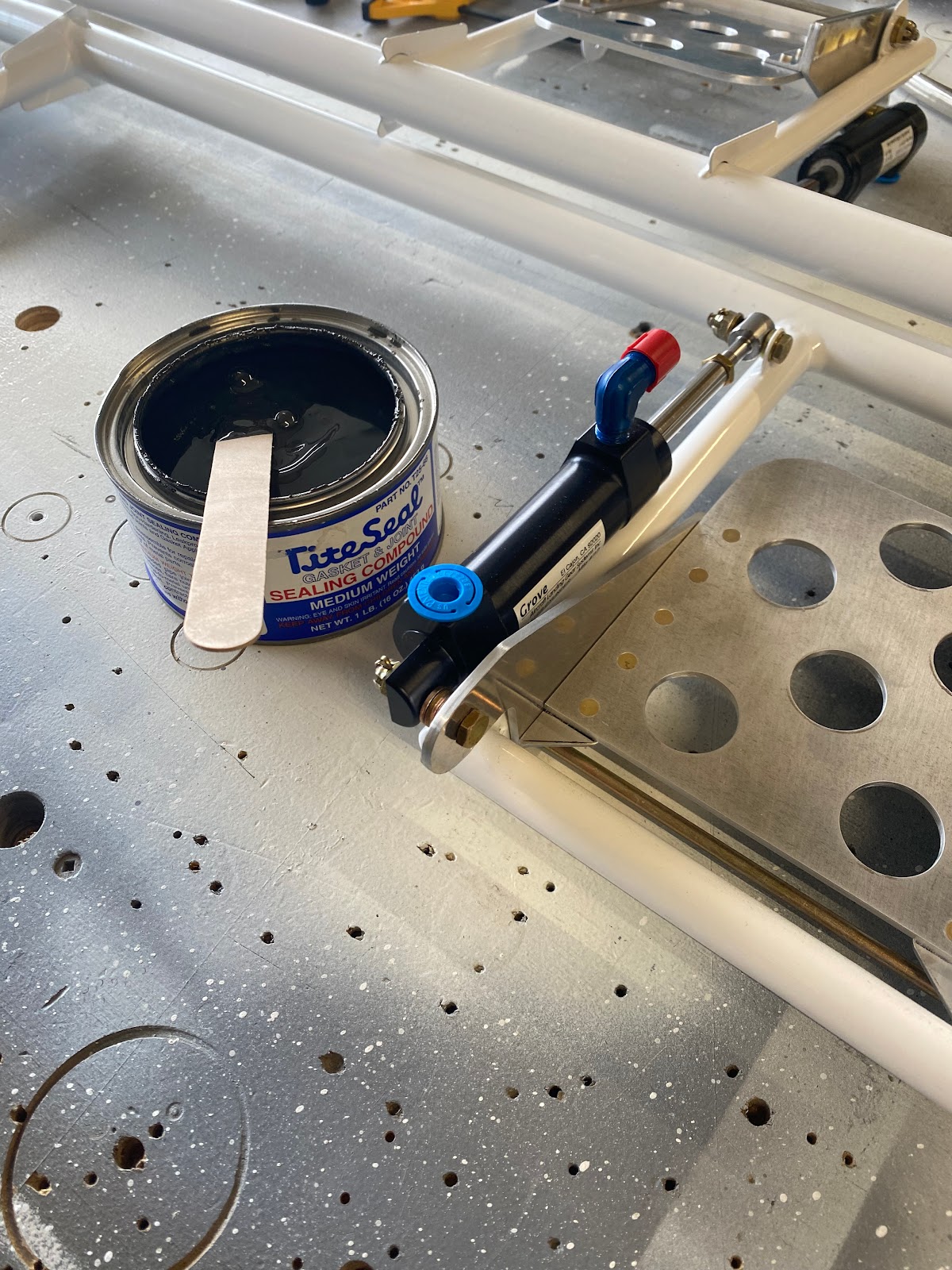
Next, I need to install eight AN fittings in the master cylinders. As per the Van's Instructions, I am using a small amount of tite-seal on the NPT threads to help seal them. 

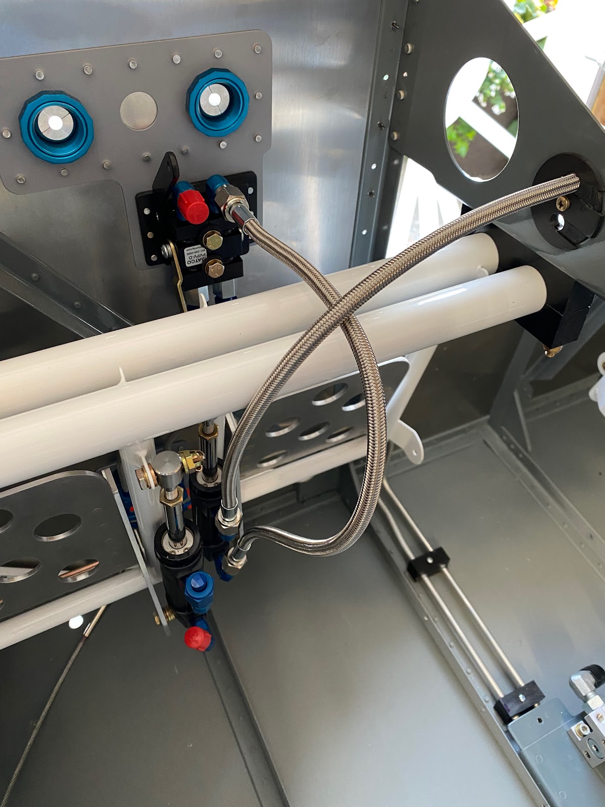
Before the brake assembly is installed. I need to finish final installation of the park brake and the park brake lines.
 

Now I am ready to permanently install the brake pedal assembly. And I can also confirm the 1/4" spacers work perfectly as it prevents any lateral movement in the assembly causing the master cylinders to touch together.  


Monday, January 10, 2022

Test fit brake line spacers - 1 hour

 I need to support the brake lines running down the center tunnel. I've seen various methods used, but none looked all that great to me. I wanted something that looks a bit more purpose built. Why not 3D print something? My co-worker Dave at the office bought a 3D printer so I designed some parts to cradle the brake lines. These are a two-piece unit that will clamp down the lines and hold them straight and tight. They also have a slight grove to allow them to next into the floor stiffener angle.


The fit is excellent!

Sunday, January 9, 2022

Finishing the brake master cylinder install and fixed center tunnel cover - 4 hours

 I moved onto finishing the installation of the Grove Brake master cylinders now that I have all the right size mounting hardware. Here is a view of the washer arrangement at the top. Took a couple of tries to get the right combination but I am really please with it. Overall the alignment is really good.


 So I installed cotter pins and called it done for now. I want to finish the final fitting of the front fuselage before I permanently install the brakes/rudder pedals. 

 With more time available to work I decided to strip the paint down on the sides of the centre tunnel since the fit is so tight with the final paint on the sides. I marked the edges where the center cover contacts the floor stiffeners. I masked off the part and ground down the metal/paint. With a couple wipes of acetone, I primed the bare metal with self-etch primer. The fit is so much better and not so tight.


Saturday, January 1, 2022

Fabricating park brake lines - 7 hours

 Well...Fabricating the park brake lines (lines that run from the park brake to the 90deg fittings) its a lot more difficult than one would think. Its just really tricky as the lines are so short, you must be precise in all your bends and cuts.


Today took a long time, but in my opinion it was well worth it. The fit is fantastic and looks pretty good. Figuring out the bend recipe was murder...I have so much scra/garbage bent tubing lol. I didn't write down the bend recipe for these as frankly I don't think anyone would; A - Need them, or B - be able to repeat it.  There were some tricky bends and some tight bends involved with these. I have to start some bends with the end of the tube on the end of the bender tool like this;

Or I have to make an immediate bend following another and I have to rotate the tube 90....slip the bend just far enough back and start the next bend.

After many many many attempts I finally was able to fabricate a left and right brake line. 


I am essentially done bending brake lines....It was so much much work but I am so pleased with the results and I have about 40' of tubing left over for future. I suppose I will give all the bending tools a good clean and light oil and I can now put them away in storage. Actually...there is quite a lot of tools that I can start thinking about putting into storage and free up some drawer and cupboard space.


Thursday, December 30, 2021

Adding more rivets to the park brake doubler - 3 hours

 Looking at yesterdays work...I think I need to add more rivets. The spacing is just too far apart. 


Adding extra rivets is not a big deal with the use of the fan spacer. 

Its looking much better now. Now I need to clean up all the corners and debur the holes, most important is to ensure a good fit of the bulkhead grommets. 
The fit is excellent so I need to dimple everything before priming. The stainless steel firewall is easy to dimple with the pop rivet dimpler. Just takes a lot of finishing nails as there are so many rivet holes now.


Wednesday, December 29, 2021

Revising the park brake location - 4.5 hours

 I struggled a bit lately on where to mount the park brake as the rudder pedal interferes with the location if I mount it in the Vans standard location. So after a bit of research, looks as if some have mounted it higher but this places it where the IO-360 mixture and prop governor control cables penetrate. So I finally decided to place the park brake in an elevated location near the bulkhead penetrations. Before I do anything, I drafted a template on AutoCAD to get the fit right before I did anything.

The initial position was too low and the result is that the brake lines interfere with the horizontal tubes of the rudder pedals.

I will need to elevate the park brake a bit. So I tested a couple of variations.

Once I was satisfied with the placement. I used the CAD drawing to cut out a doubler as the fire wall needs a bit of stiffening at that location. First step is to get the rivet holes set and the openings in the doubler sorted for the bulkhead grommets that I have. To start I used a #40 bit for all of the holes at the center points.


Using the holes in the doubler as a guide...I set the doubler on the firewall and squared it using a carpenter's square. Then I drilled and clecoed all of the holes.


Now its time to open the holes in the firewall for the bulkhead grommets.

It took some time to slowly and carefully open up the holes to final size in both the firewall and the doubler. By the time I was finished, I was really happy with the results.