Sunday, June 18, 2023

Bolting down the WD-641-PC roll bar - 2.5 hours

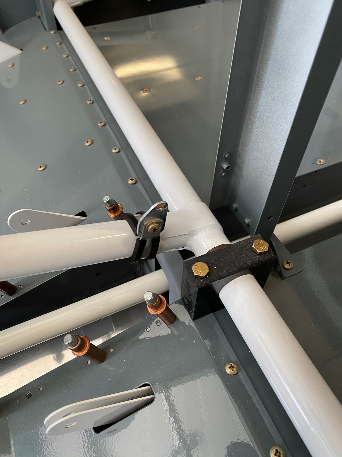
 If fitting the roll bar to the fuselage doesn't make you scratch your head, trying to bolt the roll bar (tightening the nuts) will.

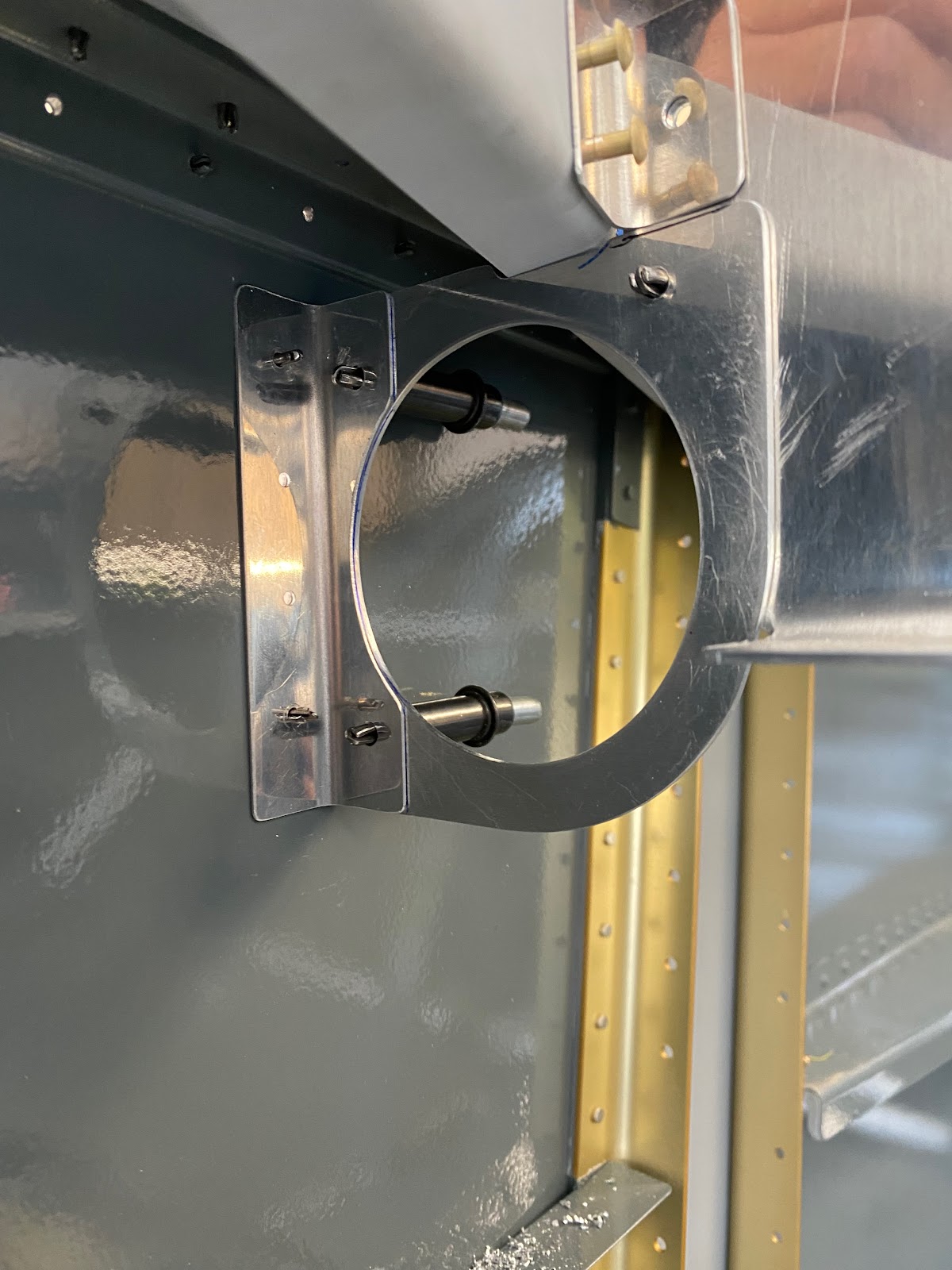
On my first attempt and fitting the canopy frame I can see that I have so work to do ensuring that the roll bar is 90deg to the longerons. I have a gap between the roll bar and the frame. 


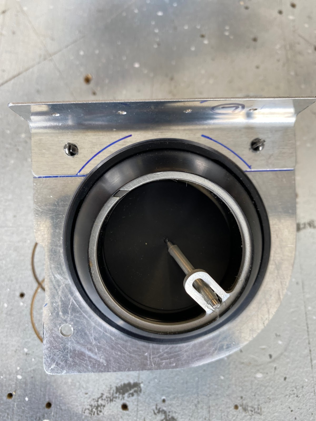
Making things more tricky is that I only have access to the AN3 bolts/nus of the roll bar. I can slip AN4 bolts into the rear mount of the roll bar, but due to the canopy deck lip accessibility to get washers and nuts on is near impossible. I need to get all bolts on and tightened if I have a hope of getting the roll bar positioned properly. I spent a few hours investigating my options, looking at special tools on the net (injector wrenches, offset sockets, etc) anything that would hold a nut in such a tight/odd space. Nothing I found would work. I see some folks on Vans Airforce forums just put a large scallop on the underside of the lip of the canopy deck allowing them to use a normal socket....This was my original plan, and went as far as drilling pilot holes in the lip. But I just couldn't bring myself to cut up so much of the lip. Between damaging the final paint and messing with the strength of the part, it was not the option I wanted. 

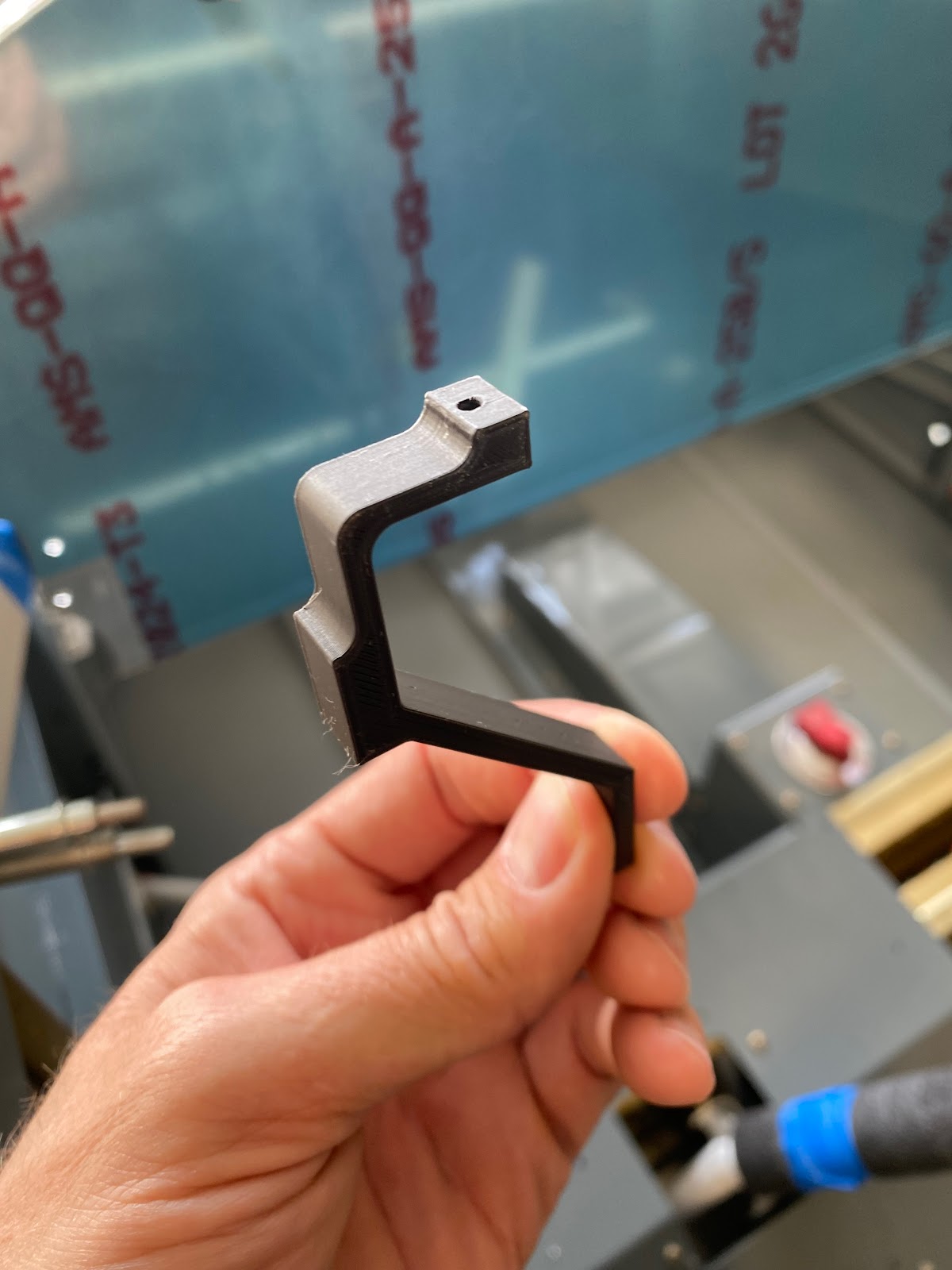
After some lunch, and a strong coffee, I had an ah-ha moment....Couldn't I just print a socket tool? I don't know why it took so long to think of this, but it could work. Assuming the plastic is strong enough? Well, I am currently using PLA+ in the printer. PLA+ is more rigid than regular PLA and its tensile strength is about double....give or take. I'll give it a shot and see.

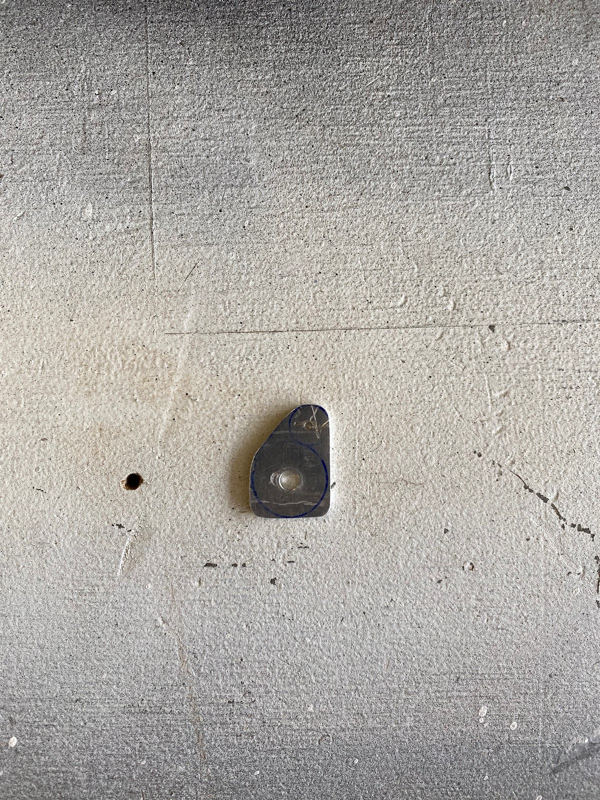
I started to create a socket shape to accept the AN4 nut.


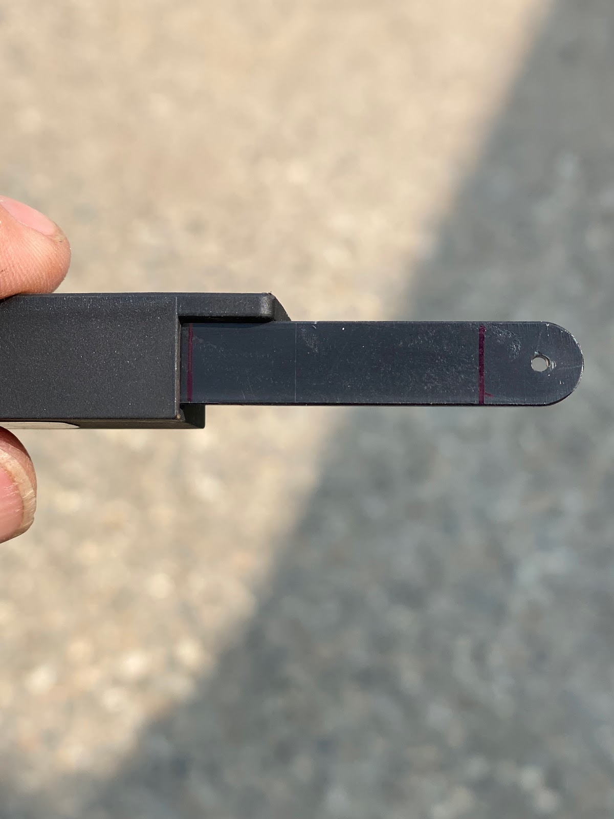
Next, I created a shape to test if I can get it to fit up under the canopy deck lip. 


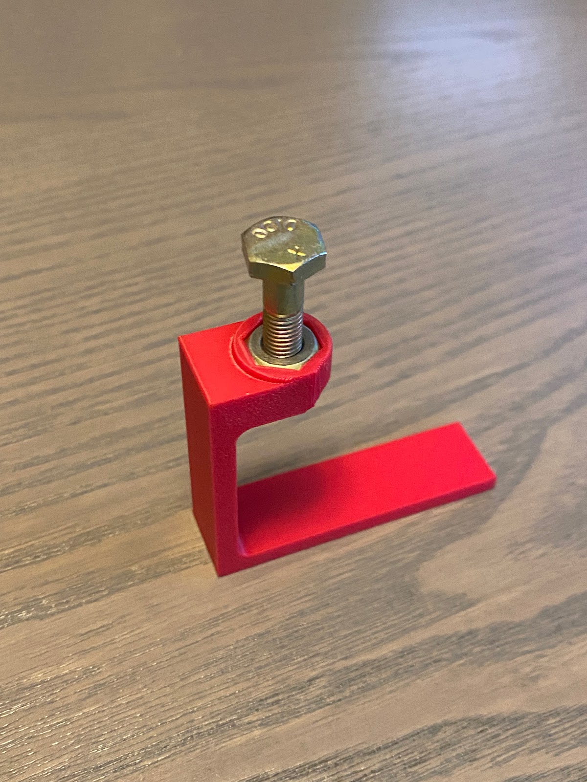
Once I had all the rough dimensions worked out, I furthered the design to allow the tool to not only hold the nut, but the washer as well. Even when so far as filleted all the tool edges and cleaned it up! 


Saturday, June 17, 2023

Drilling the holes in the Roll Bar - 3 hours

 The process of drilling the holes in the aft deck (to miss nicking the longerons) means that the #40 pilot holes in the roll bar are not perfectly aligned with the final sized holes in the canopy deck. After all, we are drilling them to final size separately. I opened up the aft mount holes in the Roll bar to 1/4" for the AN4 bolts, but left the forward holes #40. After some checks, I can see the pilot holes do not perfectly align with the AN3 holes in the canopy deck. I will have to move the pilot holes ever so slightly. 

The best way to rectify this is to make a drill template off of the canopy deck.

Eager to use the 3D printer again... I carefully made a template to fit the mount holes in the canopy deck. (Took a couple of tries to get it perfect).  


Once the template is confirmed to be a perfect fit with the canopy deck, I then mounted the roll bar onto the fuselage and clamped the template onto the roll bar. 


Taking the roll bar off, you can see the #40 mounting hole is not in the correct spot. Its just off of center from the template. 


Then using my smallest round file. I slowly...very slowly filed the hole larger and moved the center of the hole in the template. Once I got aligned much better to my liking,I was in a much better position to ream the hole to accept an AN3 bolt. (3/16") 
There is no denying this was a very long and labor intensive method, but in my opinion it was the only way to ensure precision. 


Sunday, June 11, 2023

Finishing the F-668 spacers - 5 hours

 One small task that I have been putting off for a while is fabricating a new F-668 space for the one that I lost last summer when the 3M wheel decided to take the small part I was buffing on a ride. (I was working on the driveway and the piece must have launched about 30' in the air and landed in the landscape bed...never to be seen from again. I have 2 perfect forward spacers, 1 rear spacer nearly finished but not drilled. and 1 spacer I have to make from scratch.


 Being that I have 1 spacer that is a perfect template, creating the 2nd spacer was super quick. Next...I need to start working on locating the bolt holes in the aft spacers for an AN4 bolt. The real pain working with these is getting them to fit up inside the lip of the aft canopy decks. The 3D printer comes to the rescue as I made a simple little tool. I can glue the spacer to the tool and then get the spacer up into the canopy deck to check hole alignments. 

This allowed easy checks for the hole positioning on canopy decks with the aft spacers and I could easily transfer the #40 pilot holes in the roll bar to the aft spacers. Next I opened up the holes in the aft spacers to 1/4" for the AN4 bolts.

Next, I then made a few sets of tools that would allow me to confirm the positioning of the #40 holes in the aft canopy deck. The tool I designed would allow me to get in under the lip, sit right against the fuselage and the longeron and I could have a #40 hole on the top that would (or should) line up perfectly with the #40 hole in the canopy deck for the roll Bar. 


 I made a bunch of these tools with various hole sizes so I could step up the hole from #40, #30, #19, 3/16", and 1/4". Checking the holes each time I drilled up a size. This took some time to do, but it made the outcome easy... and perfect. All holes, ended up as close as possible to the longerons without nicking them.


Saturday, June 10, 2023

More work on the Vents and Instrument sub-panel - 2.5 hours

 Today, I finished drilling the #8 screw mounting holes for the Vent mount plates in the F-793 brackets. Not much room here to drill, but my Nova tools 90deg drill comes in so handy. I am very happy with the fit and finish in the end.


During test fit of the vents I noticed there was a bit of a fit issue with the way the Stein Air vents secure with the F-793 brackets. there is a gap on one side of the vent assembly as the bracket causes some interference.


 I thought first about trimming the mount bracket to clear the vent flange, but I think that is going to result in too much material being removed.

In the end, I think the best and easiest option is to print a shim on the 3D printer, I can make a perfect plastic shim that will solve this. I will do that later in the build. 

Next I moved onto fitting the F-746 fwd engine control bracket to the instrument sub-panel.


Monday, June 5, 2023

Working on the F-793 Vent Brackets - 3.5 hours

 Now that the vent mounting plates have been trimmed, I can now work on the F-793 vent brackets. Originally I wasn't happy with my first attempt at the F-793 brackets. they were ok, but I can make them better. Since I have extra material, I quickly made 2 new ones and trimmed them up to suit the revised vent mount plates. 


After painstakingly trimming the half moon shape to allow the vents to next into them, I now need to locate the two mounting holes in each located closest to the fuselage side. Well... I put my 3D printer to work again and made a drill template to locate the holes. 


Sunday, June 4, 2023

Timming the Cabin Vent mount plates - 3 hours

 One of the things I noticed flying in a local RV7A (Thanks to Tracy for taking me up in his RV). I noticed how much space I needed for my long legs. My original plan was to locate the head phone jacks below the vents, however I realize now they take a bit of room in a critical area. I think it is very important for me to re-consider my original choice for placement as I need every inch of space I can get.  

I already have the larger 1 5/8" vents from Stein Air. I originally purchased these as they are most similar in size to the stock Vans units. So...I am going to keep those. I decided I am going to trim off the extra tab on the vent mount plates that was reserved for headphone jacks. I'll find somewhere else to put them later.


 Best way I figure to trim a nice clean line is to print a cutting template on the 3D printer.


I have a nice clean line/guide that is perfect dimension allowing me to to trim and reshape the vent mount plates.


Monday, May 22, 2023

Mounting the flap position sensor - 4 hours

 Before I start mounting things, I need to fabricate a control horn that I can mount to the WD-613-EF flap weldment. There's no real dimensions to work from, but from my initial prototypes, getting the control horn mount point closest to the center of the pivot point of the weldment is needed. So I made site the control horn was asymmetric. 


Next I marked lines on the flap position sensor to note the maximum and minimum travel limits of the sensor. 

I temporary clamped the assembly to the backrest brace and then used a 12V battery to raise and lower the flaps. Eventually I was able to dial in a sensor position and rod linkage length that would allow the flaps to travel to reach both min/max limits on the sensor.   


 I completed the final fitting of the control rod linkages, marked the sensor mount positions and drilled for #6 screws and bolted the assembly to the back brace. Everything works perfect!