Please note:
This blog is for reference purposes only. It is a record of my personal experiences and thoughts which are based on very limited knowledge during my build process. All construction, details, hints, etc that are mentioned within this blog are based on my particular set of circumstances and are all based on my very poor ability to accurately covey situations and practices in writing. So ultimately....I could be very wrong, despite my attempts to be accurate. Please keep this in mind....What works for me, does not mean that's what you should do. ALWAYS refer to the VANS manual, drawings, published mil-spec practices etc for the build of your own aircraft. These are the correct and documented methods one should follow.
If you do choose to take into consideration any of my blog material I ask a few things. 1. Please do your own research and ALWAYS follow the drawings and manuals. When in doubt...Contact VANS Technical Support. 2. Please do not copy this material, both writing and pictures (unless written permission by myself is granted) 3. As long as the reference is properly credited, please feel free to link to this site instead.
Wednesday, March 9, 2016
Research of the tank access plate
Looking at the various build logs, there seems to be a good amount of deviation from the plans with respect to the nutplates used to secure the access plate and the screws. NAS 1473-A08 nutplates are encapsulated version of the K1000-08 nut plate. There are use to mitigate the risk if leaks prom the tank attachment points. I've checked Vans Airforce and my buddy Mike, and all seem to agree that they are expensive but really good. I think i'll put and order in to Wicks and have it delivered to Vegas while I am there in the next while.
For securing the access plate, sounds like the standard AN515-8R8 screws are too short for these and longer ones are needed. Some say go with a screw head other than phillips as they are easier to remove and less prone to strip. I also read that cadmium plating is recommended for bolts/screws instead of stainless steel. Not sure if this is in fact true or not, but i am looking at using NAS1801 hex head screws as an alternative.
For securing the access plate, sounds like the standard AN515-8R8 screws are too short for these and longer ones are needed. Some say go with a screw head other than phillips as they are easier to remove and less prone to strip. I also read that cadmium plating is recommended for bolts/screws instead of stainless steel. Not sure if this is in fact true or not, but i am looking at using NAS1801 hex head screws as an alternative.
Tuesday, March 8, 2016
Layout of the tank inboard rib - 1 hour
This is something that I have been scratching my head over for a couple of days. How best to layout the stiffener ring and the tank bracket. The main concern I have is if I need to worry about edge distance to the tooling holes in the rib when I drill the new holes.

I can rotate the stiffener ring so that the tooling hole is centered between the nutplate mounting holes, but then this affects how my anti-hangup guide attaches. I may need to research this more.
I also need to pay attention to how much clearance I have with the T-405 tank angle with respect to the rivets that will attach the skin. I think it is best that I locate the AN470AD4-7 rivets such that I have enough edge distance in case I have to grind down the tank angle to allow clearance for the skin rivets.
Next challenge is the fuel flop tube hole with respect to the other tooling hole in the inboard rib. Its quite close...hmm.


Monday, March 7, 2016
Cut the access holes in the inboard tank ribs - 1.5 hours
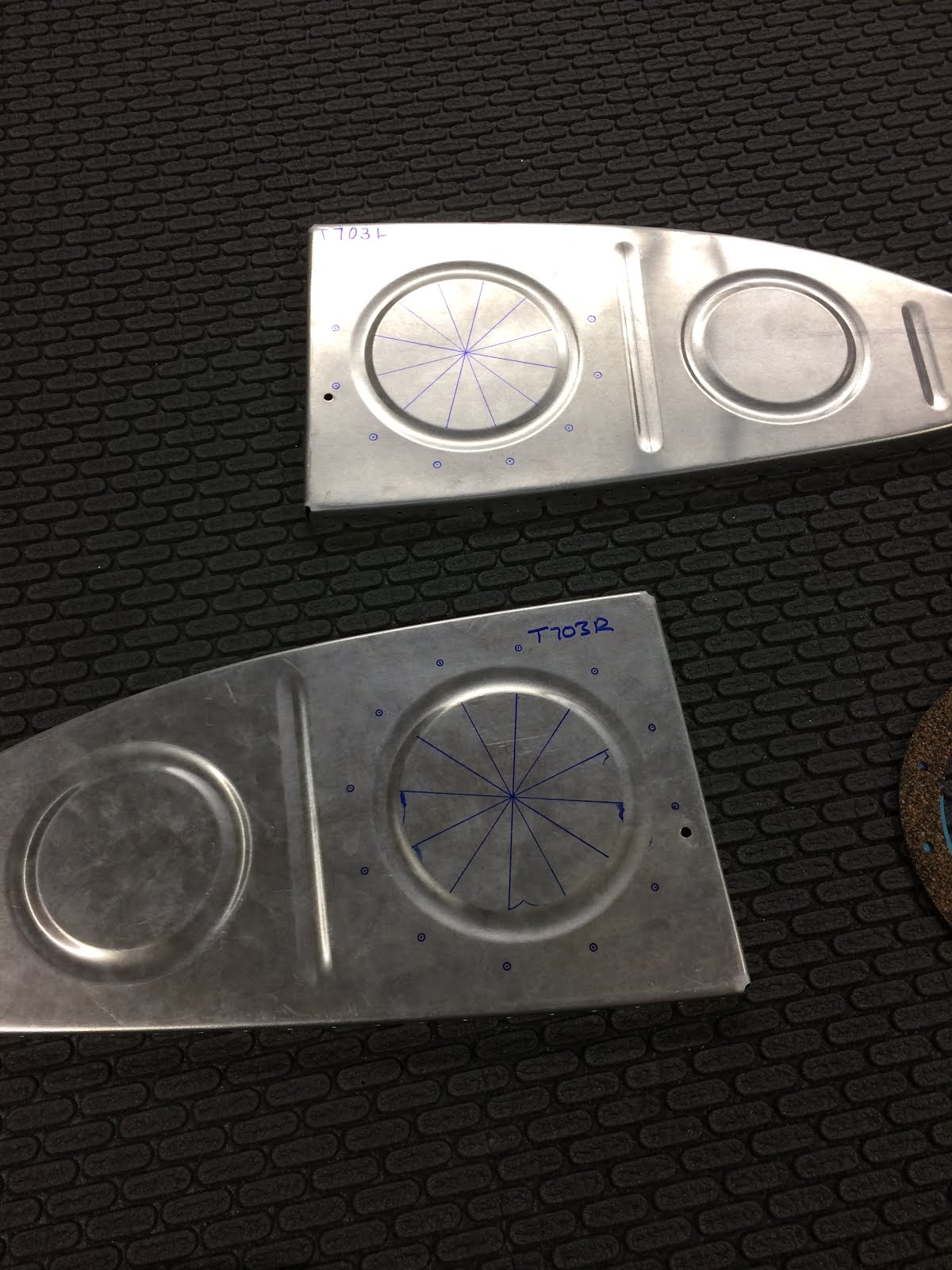
The next step is to cut the access holes in the inboard wing tank ribs. In order to do this, i needed to find the exact center of the hole. Not an easy feat. I decided to use the stiffener ring as a template to find the center. I transferred the screw holes onto the rib, and then using a ruler I drew a line from one hole to the opposite hole. This allowed me to find center

Next I used a punch, marked center, and then drilled a pilot hole to #40. Then opened that to #30. Now I was ready to use the fly cutter. I set it up on the drill press with a piece of scrap wood. Slowly i began to cut the hole. This really was a pain in the bottom as the fly cutter is not easy to use. Very nerve wracking as it is not stable and it seems very dangerous. After a while the holes did finally get cut and it ended up ok. The holes are nice and round, not the smoothest edge so a bunch of time was spent with files to take down the rough edges, then the 3M wheel came out, then scotchbrite.

Next I used a punch, marked center, and then drilled a pilot hole to #40. Then opened that to #30. Now I was ready to use the fly cutter. I set it up on the drill press with a piece of scrap wood. Slowly i began to cut the hole. This really was a pain in the bottom as the fly cutter is not easy to use. Very nerve wracking as it is not stable and it seems very dangerous. After a while the holes did finally get cut and it ended up ok. The holes are nice and round, not the smoothest edge so a bunch of time was spent with files to take down the rough edges, then the 3M wheel came out, then scotchbrite.

Sunday, March 6, 2016
Matchdrilling the left wing tank (Again) Researching fuel return lines - 4 hours
Spent the morning working away on the left wing tank. The tanks is all cleco'd so I just need to match drill the holes and countersink the baffle rivet line.


I countersunk exactly the same as before.

I then drilled the drain flange. It took some time to figure out how to center the flange on the factory punched hole in the skin. After some trial and error. I found that the center punch worked perfect as its taper ensured the smaller drain flange hole sat perfectly in the middle of the larger factory hole.


P.S I know that the flange goes to the outside of the skin and not the inside as shown. Its just easier to work with it this way.
I spent the evening researching the details needed for the fuel tanks with respect to the flop tubes, fuel return lines, and fuel sender locations (with the flop tubes).
The burning question is do I need to install the fuel return line? The information is not exactly clear, and most build sites have the fuel return line. But the item that concerns me is what roadblocks will I run into placing the return line in through the root rib. Will I hit something?
So far, from what I can tell if I go Bendix or Precision fuel injection, no return line is needed. Since I plan on using an Aerosport Lycoming Clone (Which use the Precision FI) or a stock Lycoming (Which uses the Precision or Bendix). With the AFP system, a purge line/valve tees back into the flow line (before the selector valve), so you don't need return lines in the tanks.
ECI fuel injection uses the Return lines. Return lines if installed are typically placed away from the pickup to prevent 'frothing' in the tank which could get sucked up into the pickup and maybe introduce air into the line. Usually a couple bays over is fine.
Saturday, March 5, 2016
Matchdrilling the right wing tank - Again - 4 hours
Assembling the wing tanks was much easier this go around than compared with the last time. I cleco'd the couple leading edge holes first and then worked each side from front to back.
I was very pleased with the alignment. I used a #19 reamer to match drill the holes (again) and i was careful that the holes in the ribs and baffle are not oblong due to the second go. I then set the countersink cage and countersunk the skins exactly how I did it before. Aiming for a 0.162" diameter countersink.


All done with the right tank, so I began to cleco the left tank. All I need to do is match drill the tank and match drill all the stiffeners. I'm just about back to where I was.
Friday, March 4, 2016
Dimpling the new tank skins - 3 hours
I waited thinking that my #19 reamer was going to arrive, but it didn't. So...I guess ill have to go to plan B on the tank skin holes. I decided to use 400 grit sandpaper on the dremel and open the #20 holes to #19. Its quite a tedious process...took 2 hours to do all the holes themselves. I know that I am deviating slightly from my test holes by increasing to 400 grit, but I feel confident it will be ok. The abrasive wears down quickly anyway to its only 400 grid for the first hole or two, but then it smooths out.
I then used my dimple die and made sure that each hole was large enough for the pilot, and re polished holes as needed. The benefit to all this was that there were virtually no burrs using this method.
I sprayed the piece down with WD40 and lubed the dies. I started to dimple with my stomach in my throat. In the end. Every dimple was perfect! The dimples did have sharp edges though as the holes are so crisp. I'll have to do something about that
I used a maroon scotchbrite pad on the dremel and buffed each dimple.

Subscribe to:
Posts (Atom)