Friday, October 3, 2014

Completing the drilling of the right side HS - 5 hrs


I had a decent Friday. I cleaned up the garage a bit. I have a storage locker now so I can put the Porsche away for the winter along with everything else that's in the way and make a permanent home to work in the garage. Now only to deal with the coming cold!!!
I started off buffing the ribs to ensure that I don't scratch up the skins. I then cleco'd the HS section together (left side) 

Took a skin out and cleco'd it on. Something was just not right. Everything lined up well enough, except that the HS-707 rib sat off the skin about 1/8" on one side. I just couldn't get it to lay down right. I removed the cleco's and tried again. Little better....but not right. So I switched to the right side HS assembly. Same skin....everything cleco'd up really nice. (Muhhhaaahahahah) Well....1 side is good. Let's hope the other side works out later. 

 I should note that I removed the blue vinyl from the inside of the skin before I started cleco'ing. I read on the forums somewhere that leaving the film on can sometime cause havoc in lining some things up. I can see how it can play a part, and after the issues I had with the vertical stabilizer, I removed the film.Once I had the skin cleco'd on I started in on the HS-00005/00006 ribs. I went very slow....very methodical with lining things up. It's really tough to get the HS-00006 rib to sit nice and tight into the nose of the skin. But I found that using an allan key in the grooves of the rib, I could slowly work at pulling the rib into the nose as well as getting the rib straight. after messing around, I ended up drilling the #40 holes as shown in section D-D of the HS plans. Thank God that I didn't screw that up!!! nor did I have ANY issues with edge distances. 


 I also ended up getting HS-00005/00006, HS-702, HS-710 & HS-714 nice and tight!. It took a long time to work at it, but  I can say that everything turned out very well. 

Thursday, October 2, 2014

Tinkering - 2 hours


Took an easy evening. Been very busy at work and the motivation to get out in the garage was low. I cut the hole in the front HS spar for the electric trim cable. I then scratched my head on where to put the hole in the rear HS spar. A quick check on the forums notes that the cable for the electric trim routes up and over the rear HS spar....Moving on. 


I decided to countersink the Vertical Stabilizer spar (Where it meets the fuselage) and the Horizontal Stabilizer (Center portion where it meets the HS-710/714). I cut a small piece of aluminium sheet and drilled a #40 & #30 hole and dimpled them. I used this little homemade template as a guide to check countersink depth to ensure that both parts nest well.

 It took me a while to slowly get the countersink depth down to where it needs to be. I can see where folks recommend extra countersink cages so once you have one set....you leave it as-is.


A handy little tool

I have to say a great tool that has become so handy is my Steadtler circle template (Found in the drafting section @ Staples). Its an old school template from the days of manual drafting. I find it really great to use on the project on things like minimum edge distances, layout, center lines, etc.


Wednesday, October 1, 2014

Still working on the HS front spar - 2.5 hours

Started in on working upon the HS front spar. I drew Center lines on the front spars to ensure that everything was straight. I marked out the lines for the doublers and then clamped the doublers to the spars and match drilled the holes #30.

I cleco'd the angles to the spar and completed match drilling all the holes. The holes turned out perfect with the exception of a couple holes just inboard of the bend line (the middle of the group of three closest to the bend line). The middle hole of the group is just a fraction of an inch out of line as the adjacent holes since I was not perfectly plum with my had drill. Very minor and not an issue but it's the only negative.... I'm really pleased with how it's all turned out.  


I continued on with the HS-701/714 and bent them to 6 degrees. I found that my cheap protractor was a bit to cheap and unreliable. So I drafted up a 6 degree guide on autoCAD and printed it out and used that. The bends all turned out great. I then trimmed the excess of the ends and used the scotchbrite wheels to clean them up.

Tuesday, September 30, 2014

The HS is back on!! - 4 hours

The replacement front spars arrived from Vans! Wow that's quick....wow that was expensive shipping!! Going to have to save those up and be more efficient with my shipping.

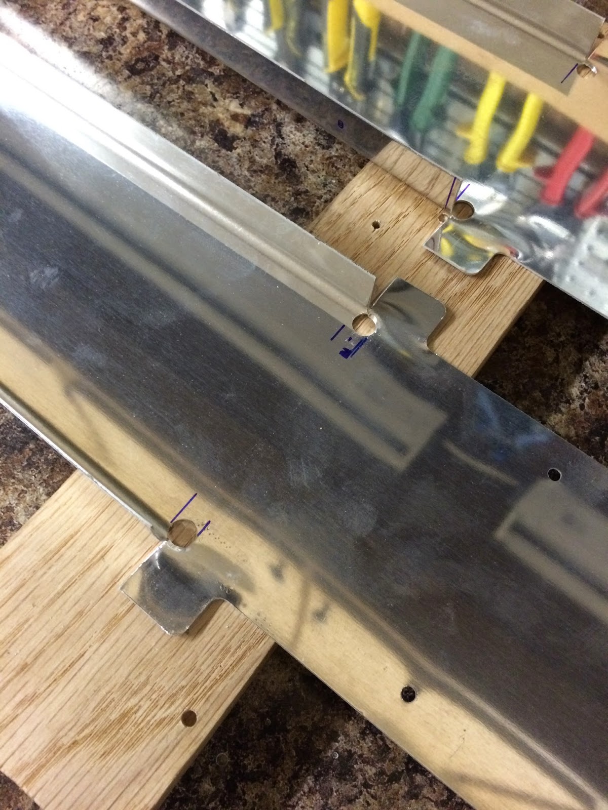
I started work on laying out the required notches and cut then. My pilot holes where pretty close. I'm still have a tab bit of an issue getting the holes started right where I need them to be. I tried to use a small punch (with push pressure only) give myself a start point, but the drill still walks a tad due to the #30 pilot hole being so close to the rounded web. In any case I used a small round file and sorted the holes out and finished off with opening them up to 1/4" with a unibit. I then cut the flanges with snips and then flattened the flanges out. I used files to slowly and carefully open the notches and fillet them. I cleco'd the spars to the skins to mark the location of the last rivet hole in the skin (next to notch)  and then used a circle template around it to ensure maximum edge distance. After all was done... I was extremely pleased with how nice the spars turned out.


I was done working in the garage so I retired to the basement and finished off de-vinyling the elevators. All of the skins have now been de-vinyled. I have to say that it was quite relaxing and enjoyable once I figured out the 700 deg temp setting, the right iron tip, and the right speed. I could sit in front of the tv and just work away.

Monday, September 29, 2014

Two steps forward. Two steps back! - 3 hours


I started the day with a phone call to Van's to double check with the Vertical Stabilizer concern. They assured me all was ok if I used scotchbrite to remove the scratches to the alclad made by the nose and tip ribs. As long as I prime the spot all will be good. I ordered the HS front spars that I messed up and they will arrive by the time I get home from work tomorrow. When I got home from work started again on the rudder. I enlarged the hole in the R-904 Bottom rib and then proceeded to cleco all of the assembly together and then I matched drilled the holes. I see that I have two extra holes in the R-606PP plate the and the R-405PD horn. The holes don't show up on the plans, and a quick search on the forums yields nothing. It seems logical that these are for extra rivets for reinforcement so I match drilled them and intend to used the specified AN470AD-7 rivets.
Oh Wait....I missed one step. I didn't radius the R-405PD rudder horn to nest against the R-904 bottom rib. Started to take the assembly apart and noticed that because I match drilled everything. The holes attaching the bottom rib to the R-902 spar are oblong. Crap....(I just put in an order to vans this morning...Crap). Well I checked everything else and the holes for everything but the bottom rib are spot on. I guess I will have to replace the bottom rib.
I think from now on its best to work as much as I can on all the assembly and save up my needed replacement parts and group order them!
I give up for the rest of the night.....Tomorrow is a new day!       


After a couple of hours break....I couldn't help but keep working at it, so I de-vinyled the rudder skins

Sunday, September 28, 2014

Started the rudder - 3 hours


Just didn't feel like putting in a big day today. Cut the R-915 stiffeners for the rudder. Trimmed them to size and cleaned up all the edges. I'm quite pleased on how they turned out. I cut the R-917 Shim. It's hard to figure out which scrap I should be using for all these custom fabricated pieces.