Showing posts with label Flaps. Show all posts

Monday, May 22, 2023

Mounting the flap position sensor - 4 hours

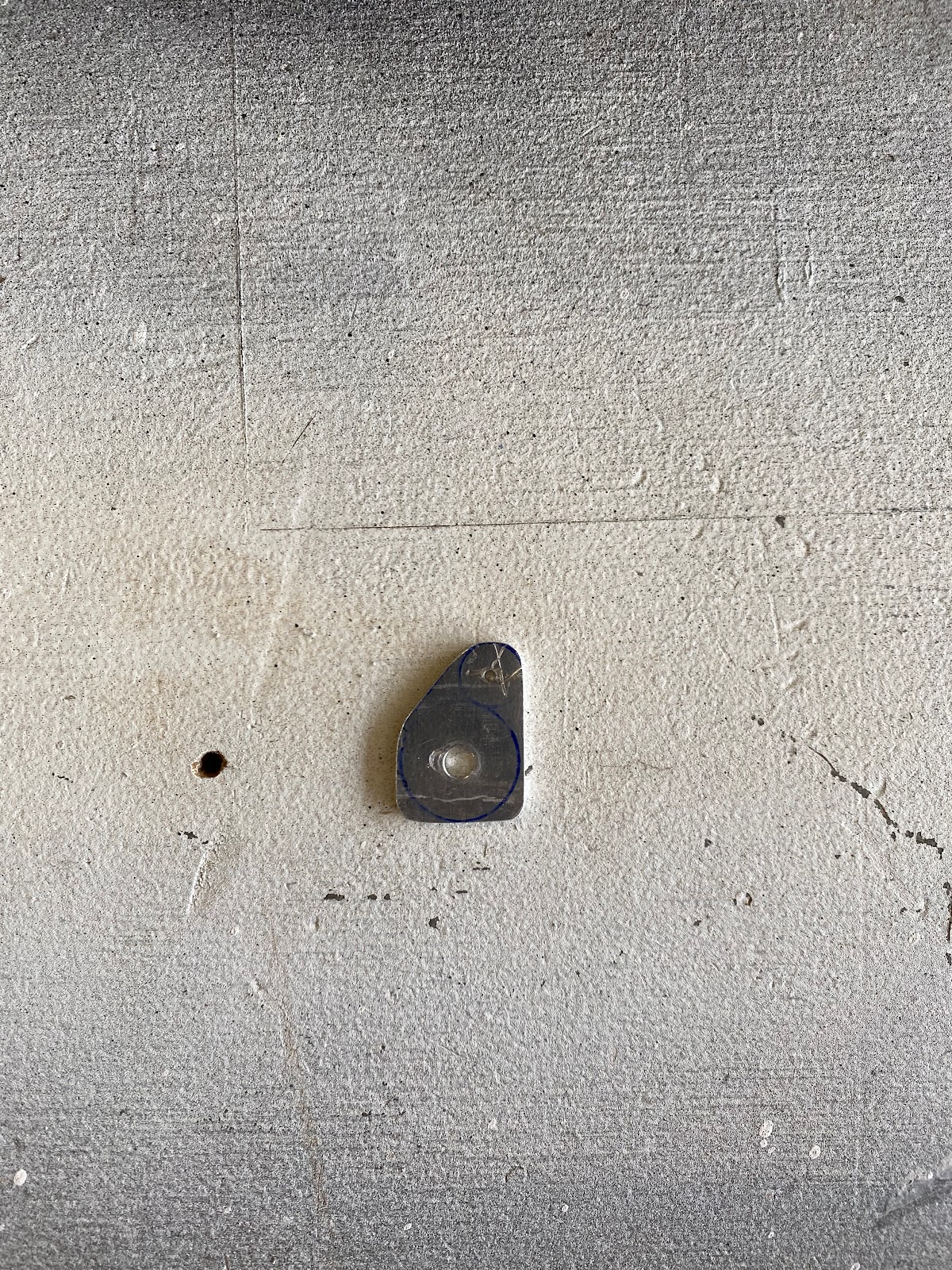
 Before I start mounting things, I need to fabricate a control horn that I can mount to the WD-613-EF flap weldment. There's no real dimensions to work from, but from my initial prototypes, getting the control horn mount point closest to the center of the pivot point of the weldment is needed. So I made site the control horn was asymmetric. 


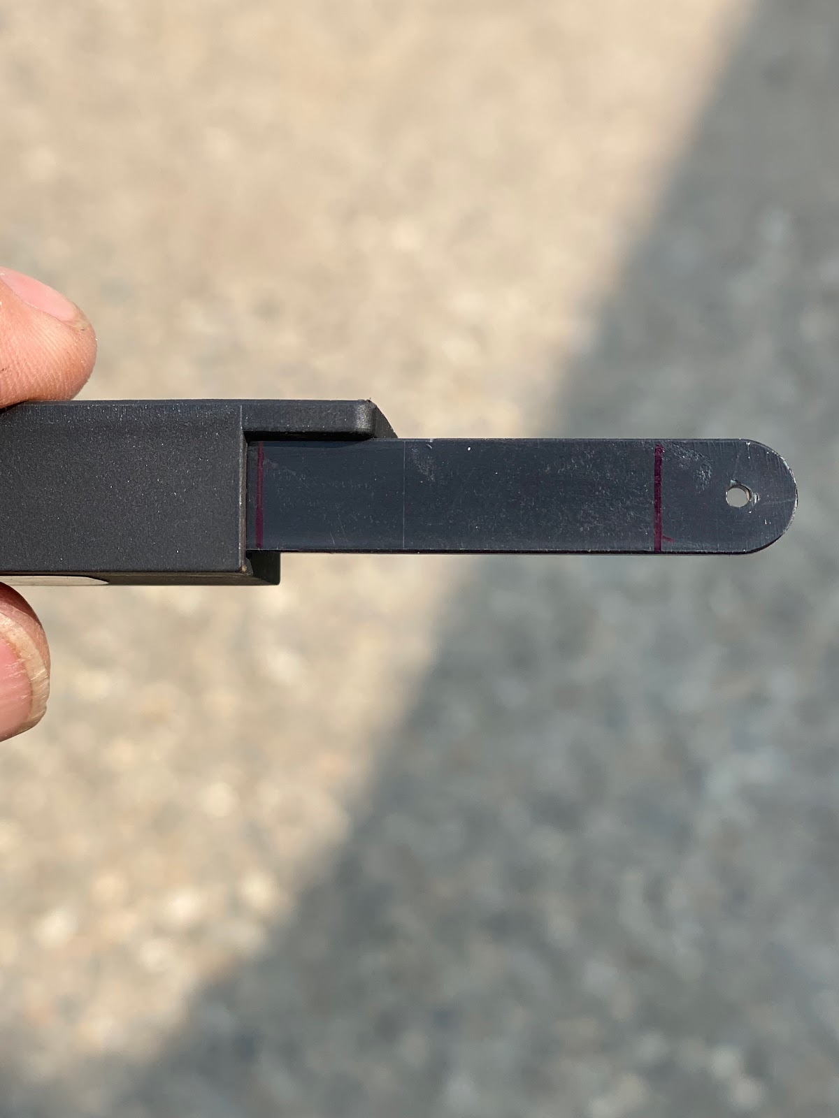
Next I marked lines on the flap position sensor to note the maximum and minimum travel limits of the sensor. 

I temporary clamped the assembly to the backrest brace and then used a 12V battery to raise and lower the flaps. Eventually I was able to dial in a sensor position and rod linkage length that would allow the flaps to travel to reach both min/max limits on the sensor.   


 I completed the final fitting of the control rod linkages, marked the sensor mount positions and drilled for #6 screws and bolted the assembly to the back brace. Everything works perfect!


Wednesday, May 10, 2023

Created angled mount for flap sensor - 3 hours

 One of the things I have been messing with for the last 6 months is 3D printing. I decided to design and print my sensor mount out of PLA plastic. The advantage of 3D printing is that I can make almost any small plastic part I would ever want, the disadvantage is that the PLA plastic is that it gets soft at temperatures at or above 60degC. So I have to be careful if where I use it. For the flap position sensor, I don't believe there to be an issue. As well, once I have the mount design I can easily print it in any number of various materials including those with higher heat ratings, and carbon fiber infused filaments. Thankfully Ray Allan Company provides excellent CAD drawings for the sensor. 


 I then could spend some time and work out the best angle for the sensor basically by printing a number of different prototypes and try each. I finally settled on a mount angle of 17deg. As well, I opened up the mounting holes in the sensor to allow for a #6 screw/bolt. 


Sunday, May 7, 2023

Planning to mount the flap position sensor - 3 hours

I spent a couple of hours today planning on how I am going to mount the flap position sensor in the center console. This also included a run to the local hobby store to buy some 4-40 threaded rod and clevis ends as suggested by the Ray Allan instructions. 

 I really like some of the mounting options that folks have shown on Vans Airforce with an angled mount. In my opinion this gives a great action to the flap sensor mechanism. I decided to start designing an angled mount.


Sunday, January 16, 2022

Installed brake line spacers and the flap actuator - 3.5 hours

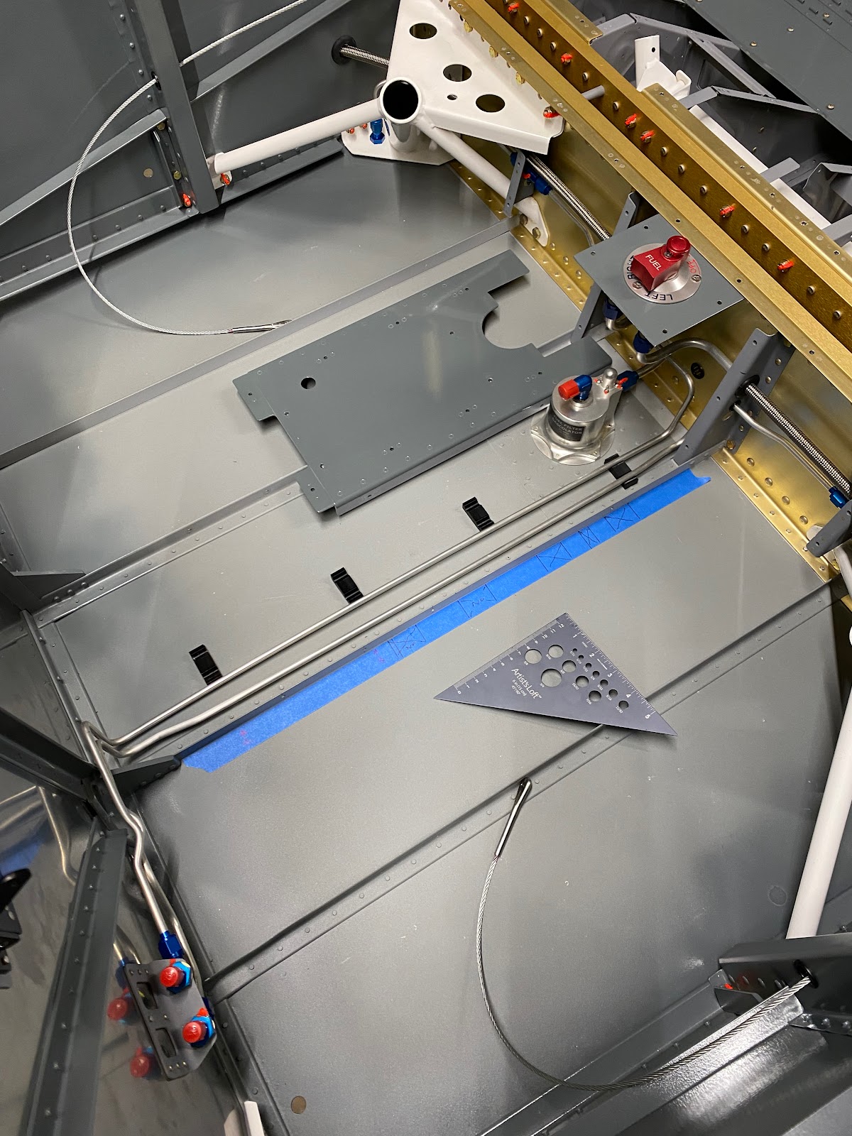
 I started to install the brake line spacers that I had 3D printed. It takes some time to lay things out. I need to ensure that the spacers do not interfere with any of the many nutplates and screws. Lots of head scratching on this task.


I also need to use the drill press and drill mounting screw holes to clamp the lines. Originally, I was going to just proseal the lines on. But I do want the ability to change lines out easily if needed, so small screws are the way to go. I raided my pinball parts stash and found very small machine screws that will work well! A little bit proseal is mixed and the bottom half of the spacers are installed.

While I wait on that, I decided to move on to the cabin area flap actuator. I just want to get the cabin put together. Easy enough I put the mounting bolt in to the assembly. And the cotter pin is set. 


 A few more screws and the flap actuator are installed. 


Work is getting soo busy I am going to have to put the build on hold for a while. It’s bitter-sweet as it’s good to be busy, but I really need to keep building. 

Saturday, January 15, 2022

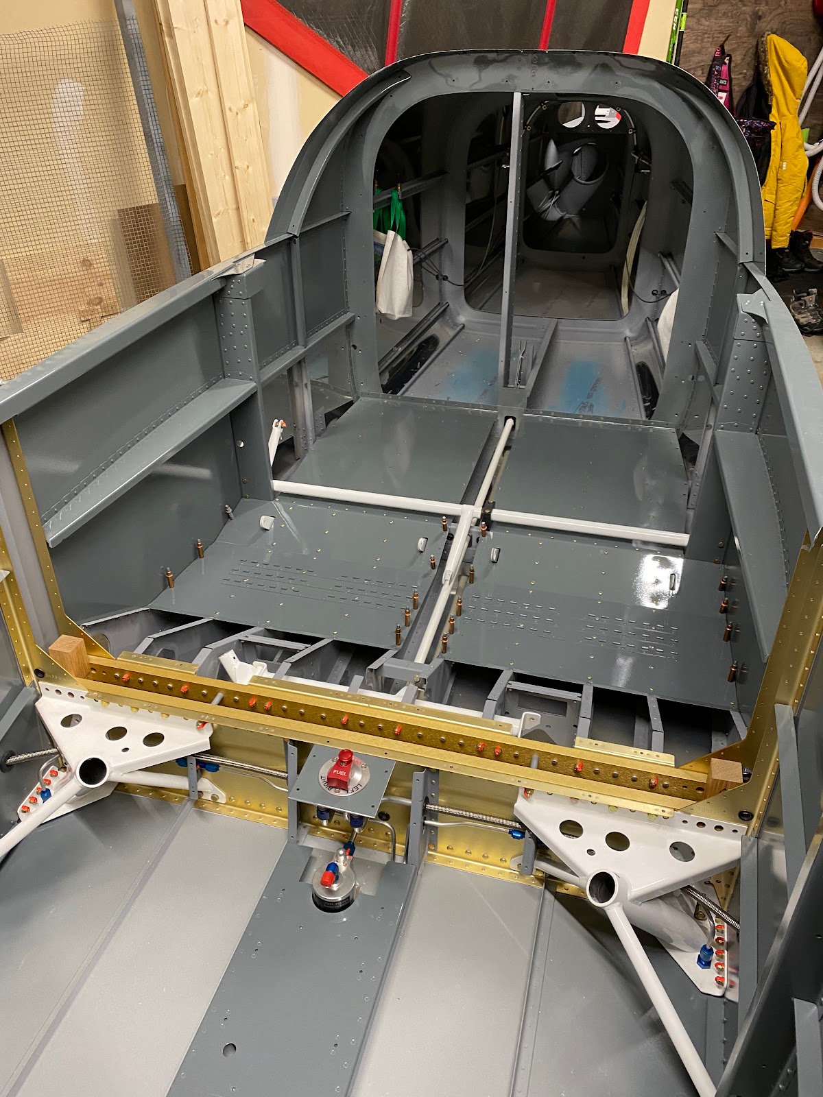
Installed the weldment….The second one - 2 hours

 I finally managed to get to the second flap weldment in the winter after messing up the first one. I ordered one back in around March/April '21 but didn't receive one until September '21. Through a mistake in ordering I actually received (and paid) for two. Good lord. Well, lets get this thing in there.

I carefully opened up the holes in the weldment  with the drill and finally with a reamer, with much better results then my first attempt. The holes for the bolts are very snug with no play. Much more acceptable. 


 In it goes into the cabin area. Looks great.


Saturday, May 8, 2021

Flap system and tunnel cover work - 6 hours

 I need to re-do the F-785A backrest brace. Originally I had drilled it for the stock RV backrest, but then after installing the Almost an RV14 mod the holes are not the same. I'm sure I could leave it as-is and carry on but it bothers me to leave it like this. 


So, I ordered a new piece and began the fitup process again, but this time with the holes for the almost a 14 mod only. 


 After the backrest brace is all set-up and redrilled. The fit for the seat mod is turning out extremely well. I do have to mess a bit with bending the tabs on the stainless backrest crossbar to tweek the fit, but in the end a have an install I am really happy with. 


Now I'm ready to finish the tunnel cover. With the flap assembly complete, I've focused a bit on the final fit of the F-741A z-channels. There is a bit of interference between the rivets on the flap channel and the z-channel. I will have to remove some material so that these parts do not rub.

Next I need to fit and drill the F-741B cover to the z-channels. However I notice that the width of the cover as called for in the plans (2 3/4") is not enough to fully span the width of the tunnel cover. Looks like I am short about 1/8" on both sides. 

So..what to do. 3 options..1 - Leave it, 2 - Make new F-741A z-channels, 3 - Make a wider F-741B cover.  Ultimately since I have spare lengths of z-channel I went with option #2 and I have everything re-cut after about an hour worth of work. I started drilling the new holes for the #8 holes and drilled one too large with a 1/4" bit. Just not paying attention. So annoying. So I scrapped Option 2 and went with Option 3. I just made a wider F-741B tunnel cover. Hopefully this works and won't be rubbing on the seat. All else fails I can always make a new tunnel cover if ever needed.


Sunday, May 2, 2021

Fixing the flap channel - 3 hours

 I was too eager to rivet yesterday and didn't look at the drawings carefully enough. I riveted the F-766C plate to the flap channel using AN470 rivets as opposed to the required AN426 rivets. Well I soon noticed the error when I started to install the flap system side covers...yup, they didn't sit flat. 

I need to drill out the 4 rivets, countersink/dimple the assembly, touch-up the primer and re-assemble. 


Now I was ready to re-install everything. Once done, it was ready for the first person to sit in the plane. It was my son Trip...who is the first official person in the plane. (And if your wondering...there's no cleco's where he is sitting...lol)


Saturday, March 13, 2021

Setting the position of the flap actuator angle - 2 hours

 Now that the mid-position of the flap actuator is set, I installed the entire flap assembly to get everything in the right place. I can find the correct angle of the assembly and drill the rivet holes in F-766B angle.

 This ends up being a tricky operation as there is a tad bit of play in the assembly. So I marked the potential rivet holes in the extremes of play in the angle. you will notice that the bottom most hole is consistent in the movement. That will be the baseline to work from. I then chose a final position to commit the other two rivet holes (represented by the black line). This black line is exactly parallel to the pre-punched holes in the F-766A channel. 

I drilled the bottom most hole to 1/8" on the drill press. Clecoed it to F-766A and then drilled the remaining two upper holes.


The other task that needs to be done is to drill the electric flap actuator for the required safety wire. Following the plans and instructions I used a 1/16" bit and drilled the hole. 


 The flap assembly is ready to go together and I began fitting the F-760 covers. 


Monday, March 8, 2021

Finding the half way of electric flap extension - 0.5 hours

 I need to set the half-way point of the electric flap extension. Using masking tape on the inside of the F-766A channel allows me to mark the correct travel and not scratch things up. I have a small 12V battery that I can test the electric actuator.


Middle position found.

Sunday, March 7, 2021

Started on the electric flap assembly - 3.5 hours

 Its time to get started on the electric flap actuator assembly. I cut the stock material for the  F-766C plate and began laying out the initial hole per the dimensions and then match drilled the rest using F-766A as a drill guide.


I'm now ready to open up the center hole to 5/8" with the uni-bit. I secured the piece to MDF backer-board as drilling operations (especially the uni-bit is more precise using it - prevents the bit from wandering).


Everything is looking great!
Next I began the fabrication of the F-766B angle. Initial rough-cuts have been made, the final shaping will be performed on the sanding station and then polished on the 3M wheel.

Next, I cut the very small/short F-766D spacer on the band saw. Working with a piece this small is not fun. Just a little difficult to cut and trim to size. I managed all right in the end. I chucked the small tube in the drill press and used sandpaper to square the ends and trim it to proper size.

I am now ready to fit up the assembly. Fit is really good.


Friday, March 5, 2021

Installing the Flap Actuator Weldment - 5.5 hours

 I'm ready to fit the WD-613-EF flap actuator weldment. In order to start I need to drill the F-680 flap bearing block according to the plans. I made a drilling template to help start the holes in the correct spot. I used a palm drill to start a hole and finish the holes on the drill press.


Next I need to trim the block down on one end.

The bearing block is ready to cut in half. Using a piece of oak as a band saw guide I am ready to cut.


The instructions have you open the clevis ends of the flap weldment to 1/4". I used drills to open up the holes with the final step using a 1/4" reamer. I'm really happy with one of the clevis ends, but the two outside clevis ends, the holes are a bit loose for my liking. It has everything to do with I used a palm drill to do the holes and not a drill press. I will order a new one and do it right. (bit of an expensive mistake). 


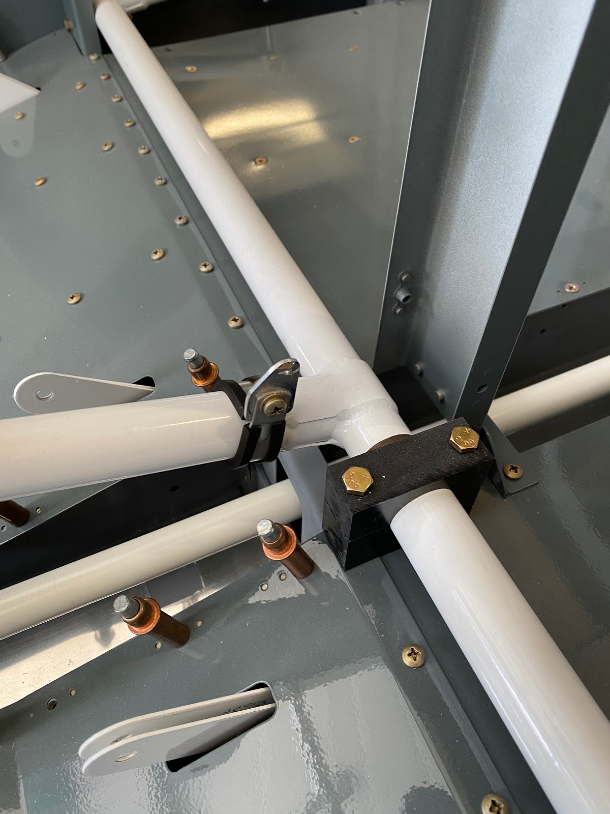
 Fitting the WD-613-EF flap actuator weldment in the airplane is a head scratch-er. In the end you have to fit one bearing block on one end. Turn it 180deg so the shortest side is pointing up. (see pic below)

Fit the weldment into the plane and then you will just be able to slip the other bearing block on the end. Turn the bearing block so the short side is pointing down (see pic below)


In this configuration, the weldment assembly is at its shortest dimension allowing it to slip into the plan. The bearing blocks are then rotated into their proper orientation and then can be bolted in place.

 I need to notch the forward edge of the F-680 bearing block. Using the band saw and going slow does a decent job.


The bearing block can now be fit and once the final location is set, I used a drillbit to dill an initial hole for the mounting bolts.

Finish the holes with the palm drill and a reamer...good to go. 
I am ready to start fitting the nutplates.