The replacement AB4-187x1 1/4 arrived so I can remake the F-711C horizontal stabilizer attach bar. Fortunately I have one completed and ready to go so it makes things very quick to so the second. I measured everything out. Placed the correct piece overtop and used the palm drill to provide pilot holes for the bottom most hole and top two attach holes. Before completing the holes in the drill press I verified the measurements of the holes.
Looking great, so I finished the holes in the drill press. Next I then cleco'd the attach bar to the F-711 bulkhead and transfer the holes. Then I completed those holes on the drill press.
Then I marked the space that is cut out on the F-711 bulkhead and cut it on the band saw.
I will have to finish these off with a file.
Wednesday, February 27, 2019
Sunday, February 24, 2019
The longeron twist - 2 hours
No magic here. The twist goes extremely quick and is very easy to do. Looking at other blogs, I used a piece of 2x4 that I cut out the shape of the angle out of the wood. It was about 2' long and made the bend very easy.
First I verified that I was 0deg before the twist.
I used the 2x4 to twist the angle. I must admit I checked about a hundred times to make sure that I was twisting the right way, the top of the angle bends in, and the bottom bends out. It only takes a few mins to get the 17deg bend.
So glad to be finished with the longerons. They got stored up in the garage for installation later.
Saturday, February 23, 2019
The sharp downward bend - 3 hours
I'm glad to be finished the big bend or curve as it was very nerve wracking. I was terrified of ruining the longeron, but in retrospect it wasn't that difficult. Just quite time consuming and a little frustrating as the plans suggest. An I too agree that its best done when broke into small segments.
Fortunately the sharp downward bend goes much quicker. I was careful not to put a sharp edge on the piece of oak that i'm using using for a bending block (its 1/8" radius) as I have found in the past bending aluminum around sharp corners can cause cracks at least with thin material....so why stop now.
I was having a tough time figuring out how best to set up for measurement of the 2 3/4" drop. I have a bike stand that I used to clamp a wood ruler onto.
It looks good in theory, but in actual fact it doesn't work so well. I ended up in the end just simply using the straight clamped across the top and using a ruler to measure the drop. The sharp bend down causes quite the bend in the other direction so ultimately the stand just gets in the way.
To promote a clean sharp bend at the 28 1/4" mark, I locked the angle down in the vice and clamps.
I began to bend, check, correct for straightness, bend some more, so on, and so on. I managed to get one finished fairly quickly. But it is time consuming to remove the clamps just to do the measurements. One all done...Measures 2 3/4" apart from the unbent one.
Now its 5 1/2" apart when both are bent, and more importantly both are perfectly aligned.
Best of all, it matches the skin perfectly.
Fortunately the sharp downward bend goes much quicker. I was careful not to put a sharp edge on the piece of oak that i'm using using for a bending block (its 1/8" radius) as I have found in the past bending aluminum around sharp corners can cause cracks at least with thin material....so why stop now.
I was having a tough time figuring out how best to set up for measurement of the 2 3/4" drop. I have a bike stand that I used to clamp a wood ruler onto.
It looks good in theory, but in actual fact it doesn't work so well. I ended up in the end just simply using the straight clamped across the top and using a ruler to measure the drop. The sharp bend down causes quite the bend in the other direction so ultimately the stand just gets in the way.
To promote a clean sharp bend at the 28 1/4" mark, I locked the angle down in the vice and clamps.
I began to bend, check, correct for straightness, bend some more, so on, and so on. I managed to get one finished fairly quickly. But it is time consuming to remove the clamps just to do the measurements. One all done...Measures 2 3/4" apart from the unbent one.
Now its 5 1/2" apart when both are bent, and more importantly both are perfectly aligned.
Best of all, it matches the skin perfectly.
Thursday, February 21, 2019
Finished the big bend on the longerons - 4 hours
I managed to work a bit more on getting bends on both the horizontal (to match the plans) and the vertical (to flatten them out). Another couple of hours of "whispering" and things worked out well.
Next step I was ready to drill the F-721B aft decks. I cut some 0.032" strips from scrap as the plans suggest. I used a tedious process of clamping, Marking pilot holes with the palm drill and completing holes with the drill press.
Things look excellent. (I left that last hole fwd undrilled) I just figured I wanted to drill it after I made that sharp downward bend as its so close to that line.
Tuesday, February 19, 2019
More longeron bending - 3 hours
One of the benefits of working in an engineering office is that I can draft the longeron bending templates to perfect full scale and also mirror them to fit both the Left and Right sides. I scanned in my F-721B aft deck pieces and then drew out the correct bend in autoCAD to 1:1 scale.
And of course the continuous roll plotter comes in extra handy.I managed to print out a 72" long paper template.
I managed to make short work of the second longeron. It goes way more quick than the first one as you now have a feel for the correct pressure needed on the bending dies, and you are not so afraid of over bending. I managed to bend the send one to near correct in about an hour or so. Then came the not so fun tweaking. The bend of the two pieces is virtually perfect on the horizontal, but not on the vertical. this shows up when you clamp the two pieces together.
Looking great here....
But not so good here....
This is where things can get a little frustrating. Trying to flatten that unwanted separation between the longerons results in changing the bend that you want to have match the template. So lots of back and forth futzing. I spent an hour on it but was making little progress, but at least I was in the ball park.
Monday, February 18, 2019
Starting the big bend! - 9 hours
Again, I spent some time reading up on other build logs on bending the longerons before I started in. I figured out that I didn't really need to make the cuts at this exact time. But it was very important to mark things out. My reasoning is (that the fuselage up to this point is reminding me) that pieces are more exact when you can fit, check, and then cut rather than blindly cut....more so around the horizontal stabilizer. I So, I dug out my thin sharpie and went to work.
I then dug out my longeron bending dies that I have bought some time ago. One of the items everyone talks about is protecting the angle from marring so I used some gorrilla tape and lubed the dies with WD-40. That works well but a pain in the butt as it wants to remove your sharpie marks.
I drew a reference line on the dies
First pass, you will notice the gentle bend.
Second pass, Third pass. Ugh... I am being careful not to overbend as the longeron dies mention but this is painful. I've been at it for hours and only small steps. I decide I can then become a bit more aggressive with the bending. Yup, bends going well now, but there is a noticeable curl up in the longeron 90deg perpendicular to the bend i'm making, which is to be expected. I went to work taking that bend out and trying get it to lay flat on the table again. Interesting, by taking the vertical bend out is relaxes the horizontal bend i'm trying to get. Hmmm, You purposely want to overbend the longeron a bit on the horizontal. Well after a few hours, of working with the longeron. I had both the horizontal curve matching the plans and laying flat on the table.
I am the aluminum whisperer.
Now...next concern was bending the other longeron and matching it up to the plans.
Sunday, February 17, 2019
Measuring longerons - 3 hours
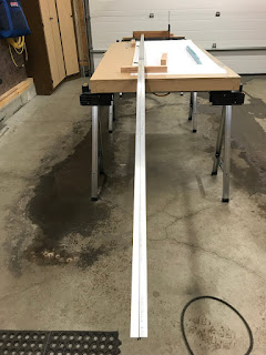
It was time to start on the longerons. These have been sitting up on the garage shelf for quite some time. They collected a lot of dust. I spent some time getting the garage ready, putting saw horse out and leveling the run to aid in accurate measuring. I cleaned up the ends of the longerons and then clamped them together and began marking out the dimensions. After a good discussion with a local builder he offered a few tips and suggestions, using the bottom skin and the aft canopy deck pieces as a guide. He mentioned that he had to trim a bit of the front of the longeron to fit the bulkhead which got me thinking about if I could get myself into hot water with edge distance issues (as was the case with the F-728/729 angles)
I spend a few hours researching and reading. Before I did anything I decided to research the whole longeron process. I was most curious about if I could run into any potential edge distance issues, seems that most folks trim about ¼” off the front of their longerons. After all my reading I decided to give myself some extra material to play with (½” extra to be exact). So I erased all my marks and drew a new reference line that would give me ½” extra. I clamped a piece of oak on the new datum point and re-measured all the dimensions out.
Riveting F-712, F-706 (again) and F-707 & F-708 - 4 hours
I woke up this morning ready to go on riveting the bulkheads together. I started with the F-712 bulkhead. I back riveted the entire assembly it turned out so good.
Funny though that after I had it all riveted is when I figured out that the plans have you hold off this step. I did not read the manual for F-712, I just assumed. I started checking off steps in the manual and that's when I noticed it.
I began to dig into who, what, why and where. Took my hours to figure out if this is going to be a problem. I finally came to the conclusion after talking to a local builder friend (and also noticed that this was done on a few other build logs - John's RV7A project, Bruce Swayze's RV7A project) that this was totally ok to leave riveted on and did not cause issues later. An angle drill is used to start the #1/8" holes into the vertical stabilizer, and of course I plan on using the drill press anyway to finish the job.
I suspect the plans are set up this way to accommodate the quick builds. Anyone with a quick build fuse (7 or 7A) gets the fuselage with nothing on the bulkhead. If you have a 7A you then have to fabricate the tie down bar and install it before you mount the vertical stabilizer. It would be reasonable that to avoid confusion they just have everyone do it later.
After all my research, I am confident that my little oops has actually turned out to be the better method of installation.
Now that I could breath easy, I moved onto riveting the F-706 bulkhead...Again.
Admittedly I struggled a bit with setting the left side rivets on the F-729 rib. On my first attempt a few weeks ago, I put the factory heads of the rivets forward, leaving shop heads aft on the web flange, the result is that it wanted to curl the web flange up. So on this attempt I put the factory heads aft to prevent the flange from curling. Much more difficult to squeeze those rivets and get them straight. After drilling them out, I decided to go for the bucking method a used the same technique as that used on setting the wing ribs. bending the rib slightly to the side and using a super long rivet set. Worked perfectly.
I completed the F-706 bulkhead. Obviously I've not riveted the F-728 and 729 angles at this time. I will do that once I can confirm perfect alignment of the bellcrank axis.
I then riveted the F-707 and F-708 bulkheads. Easy
Funny though that after I had it all riveted is when I figured out that the plans have you hold off this step. I did not read the manual for F-712, I just assumed. I started checking off steps in the manual and that's when I noticed it.
I began to dig into who, what, why and where. Took my hours to figure out if this is going to be a problem. I finally came to the conclusion after talking to a local builder friend (and also noticed that this was done on a few other build logs - John's RV7A project, Bruce Swayze's RV7A project) that this was totally ok to leave riveted on and did not cause issues later. An angle drill is used to start the #1/8" holes into the vertical stabilizer, and of course I plan on using the drill press anyway to finish the job.
I suspect the plans are set up this way to accommodate the quick builds. Anyone with a quick build fuse (7 or 7A) gets the fuselage with nothing on the bulkhead. If you have a 7A you then have to fabricate the tie down bar and install it before you mount the vertical stabilizer. It would be reasonable that to avoid confusion they just have everyone do it later.
After all my research, I am confident that my little oops has actually turned out to be the better method of installation.
Now that I could breath easy, I moved onto riveting the F-706 bulkhead...Again.
Admittedly I struggled a bit with setting the left side rivets on the F-729 rib. On my first attempt a few weeks ago, I put the factory heads of the rivets forward, leaving shop heads aft on the web flange, the result is that it wanted to curl the web flange up. So on this attempt I put the factory heads aft to prevent the flange from curling. Much more difficult to squeeze those rivets and get them straight. After drilling them out, I decided to go for the bucking method a used the same technique as that used on setting the wing ribs. bending the rib slightly to the side and using a super long rivet set. Worked perfectly.
I completed the F-706 bulkhead. Obviously I've not riveted the F-728 and 729 angles at this time. I will do that once I can confirm perfect alignment of the bellcrank axis.
I then riveted the F-707 and F-708 bulkheads. Easy
Saturday, February 16, 2019
Prep'd & Primed all bulkheads (except F-711) - 9 hours
Managed a huge day today in the garage. A very tedious process to prime that I have. Scuff parts, wash in soapy water, rinse, dry, wax & degrease, MEK, Prime. With setup and take down of the large containers for washing parts it takes a lot of time so its beneficial to prime all at once. Also I am motivated to get this done as I always like to have a full 24 hours dry time minimum to the primer before I assemble.
Since bulkheads F-706 and F-712 where ready to go, I started the priming process for those.
As those parts were drying, I needed to work on the F-710B angle. The fit of the angle wasn't the best for the tabs on the bulkhead where the longerons get installed. The sharp corner on the end of the angle needs to be rounded to allow the bulkhead, tab and angle all to sit flush.
I went to work rounding that corner. However one of the jobs I need to do is to round the top flange of the F-710B angle so it nests nicely inside of the longeron. The best way I believe I can do this is to round it once I have it all installed and can verify perfect fit. So I will hold off on riveting this part until later.
Once I finished rounding the angle for the bulkhead tabs, I moved on to prepping the F-707, F-708 and F-710 parts for priming. Lots of work to break all the edges, deburr and polish all the nooks and crannies. I opened the holes for the rudder cables (Did I ever mention I hate doing those?) and the static lines. Then it was through the long a tedious process of priming....
Subscribe to:
Posts (Atom)